Standard pneumatic
cylinders.
Profile-body, tie-rod and multi-mount short-stroke formats. Compare SI, SE, SC, SAI and MD-series configurations for the mounting, travel and interfaces of your machine.
Five series groups.
Compare the construction.
Start with the body and installation format. Open the selected series for its operating data, stroke options and configuration details.
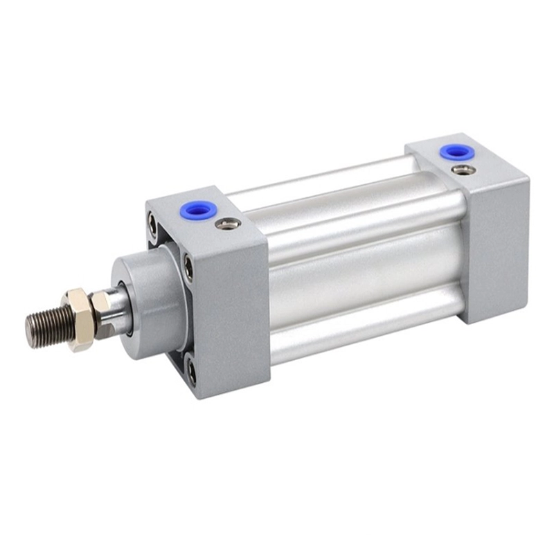
SI Series
Standard profile cylinder with double-rod and adjustable-stroke variants. Confirm the required mounting and sensor configuration.
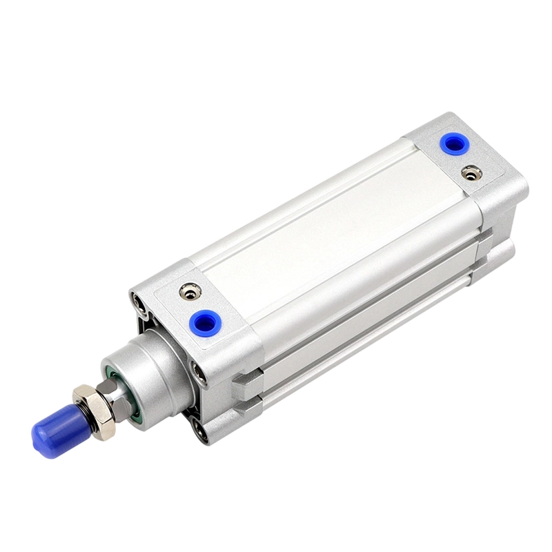
SE Series
Standard profile cylinder platform with double-rod and adjustable-stroke variants. Compare dimensions and port arrangement for the installation.
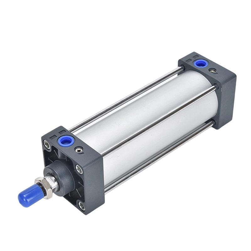
SC Series
Tie-rod cylinder platform for general industrial linear motion. Match the rod, mounting and cushioning options to the load.

SAI Series
Standard cylinder with a switch-groove profile for position sensing. Confirm sensor fit and mounting dimensions.
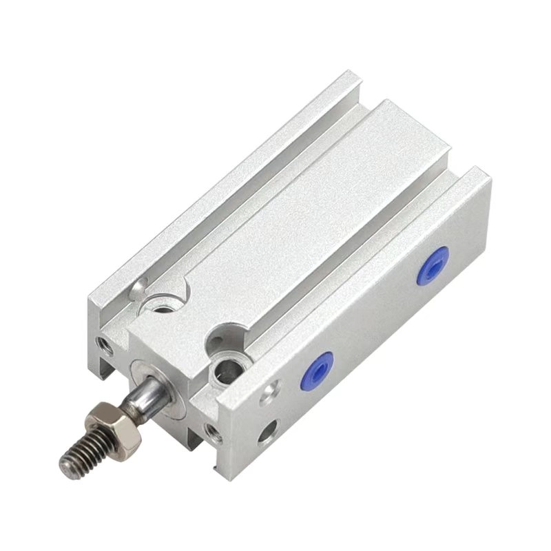
MD / MDD / MSD
MD multi-mount cylinder family; the same platform is also listed under compact cylinders. Compare MDD double-rod, MDJ adjustable-stroke and MSD/MTD single-acting configurations within this family.
Choose a body format.
Then check the fit.
Construction guides the comparison. Mounting dimensions, rod arrangement, ports and sensor fit still need to match the selected model.
| Series group | Construction | What to compare |
|---|---|---|
| SI Series | Profile body | Mounting and sensor configuration, including double-rod and adjustable-stroke variants. |
| SE Series | Profile body | Body dimensions, port arrangement and the rod configuration for the installation. |
| SC Series | Tie-rod body | Mounting and service access around the tie rods, with the required rod and cushioning arrangement. |
| SAI Series | Profile with switch grooves | Sensor fit, mounting dimensions and the port size for the selected bore. |
| MD / MDD / MSD | Multi-mount short-stroke body | Acting type and mounting surfaces. The listed MD stroke rows cover selected double-acting configurations. |
A matching series name, bore and stroke do not establish dimensional interchangeability. Check the mounting drawing for the complete model.
Series-specific
technical data.
Open a series for its operating conditions, configuration and stroke selection. Check the complete model and mounting drawing before ordering.
SI SeriesOperating data · Stroke and port selection
Scroll the table sideways to compare all stroke and port columns. Keyboard: focus the table area, then use the left and right arrow keys.
| Bore (mm) | Port size | Listed standard strokes (mm) | Max. standard stroke (mm) | Maximum stroke (mm) |
|---|---|---|---|---|
| 32 | 1/8″ | 25 50 75 80 100 125 150 160 175 200 250 300 350 400 450 500 | 1000 | 1800 |
| 40 | 1/4″ | 25 50 75 80 100 125 150 160 175 200 250 300 350 400 450 500 600 700 800 | 1200 | 1800 |
| 50 | 1/4″ | 25 50 75 80 100 125 150 160 175 200 250 300 350 400 450 500 600 700 800 900 1000 | 1200 | 1800 |
| 63 | 3/8″ | 25 50 75 80 100 125 150 160 175 200 250 300 350 400 450 500 600 700 800 900 1000 | 1500 | 1800 |
| 80 | 3/8″ | 25 50 75 80 100 125 150 160 175 200 250 300 350 400 450 500 600 700 800 900 1000 | 1500 | 1800 |
| 100 | 1/2″ | 25 50 75 80 100 125 150 160 175 200 250 300 350 400 450 500 600 700 800 900 1000 | 1500 | 1800 |
| 125 | 1/2″ | 25 50 75 80 100 125 150 160 175 200 250 300 350 400 450 500 600 700 800 900 1000 | 1500 | 1800 |
| 160 | 3/4″ | 25 50 75 80 100 125 150 160 175 200 250 300 350 400 450 500 600 700 800 900 1000 | 1500 | 2000 |
| 200 | 3/4″ | 25 50 75 80 100 125 150 160 175 200 250 300 350 400 450 500 600 700 800 900 1000 | 1500 | 2000 |
Stroke availability depends on the complete model, acting type and options. Confirm the configuration and mounting drawing before ordering.
SE SeriesOperating data · Stroke and port selection
Scroll the table sideways to compare all stroke and port columns. Keyboard: focus the table area, then use the left and right arrow keys.
| Bore (mm) | Port size | Listed standard strokes (mm) | Max. standard stroke (mm) | Maximum stroke (mm) |
|---|---|---|---|---|
| 32 | 1/8″ | 25 50 75 80 100 125 150 160 175 200 250 300 350 400 450 500 | 1000 | 1800 |
| 40 | 1/4″ | 25 50 75 80 100 125 150 160 175 200 250 300 350 400 450 500 600 700 800 | 1200 | 1800 |
| 50 | 1/4″ | 25 50 75 80 100 125 150 160 175 200 250 300 350 400 450 500 600 700 800 900 1000 | 1200 | 1800 |
| 63 | 3/8″ | 25 50 75 80 100 125 150 160 175 200 250 300 350 400 450 500 600 700 800 900 1000 | 1500 | 1800 |
| 80 | 3/8″ | 25 50 75 80 100 125 150 160 175 200 250 300 350 400 450 500 600 700 800 900 1000 | 1500 | 1800 |
| 100 | 1/2″ | 25 50 75 80 100 125 150 160 175 200 250 300 350 400 450 500 600 700 800 900 1000 | 1500 | 1800 |
| 125 | 1/2″ | 25 50 75 80 100 125 150 160 175 200 250 300 350 400 450 500 600 700 800 900 1000 | 1500 | 1800 |
Stroke availability depends on the complete model, acting type and options. Confirm the configuration and mounting drawing before ordering.
SC SeriesOperating data · Stroke and port selection
SC tie-rod cylinder selection
External tie rods join the barrel and end covers. The catalog reference separates SC single rod, SCD double rod and SCJ adjustable stroke in 32–250 mm bores from the SCT multi-position range in 32–100 mm bores.
Use the series reference to compare bore-specific ports, speed, seal codes, stroke limits and dimensions. SCT requires two stroke fields and its own installation drawing. Confirm the complete offered model and current drawing before ordering.
SAI SeriesOperating data · Stroke and port selection
SAI cylinder selection
Compare SAI single rod, SAID double rod and SAIJ adjustable stroke. The catalog reference separates the standard 32–200 mm range from SAIL locking and SAIF valve-equipped configurations.
Use the series reference for bore-specific speed, ports, strokes, mounting and variant limits. Confirm the complete offered code and current dimensioned drawing before ordering.
MD / MDD / MSDOperating data · Stroke and port selection
MD multi-mount cylinders
The MD family also appears in the compact-cylinder range. Use the same MD model reference for acting type, bore, stroke, mounting and ports.
Review the mounting.
Leave room for motion.
Check the complete cylinder, its accessories and the air connections within the machine. The selected model and installation determine the final arrangement.
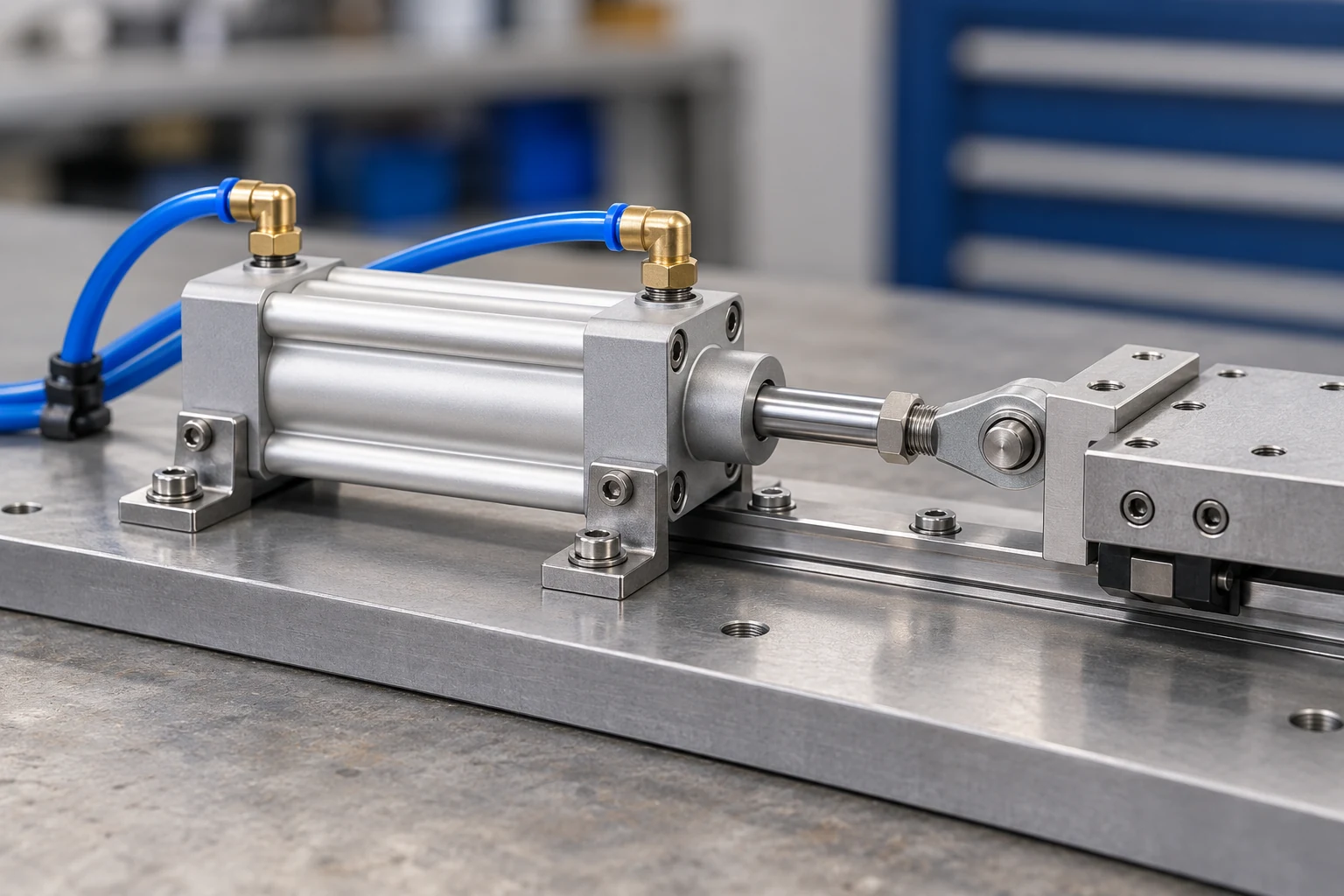
New machine
Define the motion, moving load, orientation and space around the cylinder. Record the required speed and position feedback.
Replacement
Record the complete model, bore and stroke. Compare mounting centres, rod thread, port positions and sensor fit with the existing installation.
- Profile body or tie-rod
- Compare SI, SE and SAI when a profile body suits the machine envelope. Use the SC tie-rod layout when its mounting and service access match the installation. A series name alone does not confirm replacement dimensions.
- Match bore, stroke and ports together
- Select bore for required thrust at the available working pressure. Check the stroke and port row for that bore: larger SI and SAI sizes use different port sizes and speed limits from the smaller models.
- Choose rod and cushioning arrangement
- Double-rod and adjustable-stroke variants change the installation envelope. SI, SE, SC and SAI use variable cushioning; the MD short-stroke platform uses bumper cushioning.
- Plan feedback and fittings
- Specify the magnet option when position switches are required. Confirm switch mounting, selected port thread and pipe clearance before freezing the machine drawing.
Check the details.
Prepare the requirement.
Use the new-machine and replacement checklists alongside the selected cylinder data.
Common questions.
Are all standard-cylinder series dimensionally interchangeable?
Fit must be checked against the selected cylinder drawing. Compare mounting centres, rod thread, body length, port locations and accessory dimensions; a common bore and stroke do not establish interchangeability.
How do I choose SI, SE or SAI?
Start with the machine mounting arrangement and bore requirement. SI and SAI include larger bore sizes, while the SAI switch-groove arrangement helps when sensor mounting is a key requirement. Compare the actual drawing and switch before ordering.
Is proof pressure an operating pressure?
No. Operating pressure and proof pressure are separate ratings. Size and run the actuator within its operating range. Proof pressure is a test reference and is not an operating setpoint.
What is needed to confirm a replacement cylinder?
Supply the complete existing model code, bore, stroke, acting type, mounting drawing, port thread and sensor details. Include the moving load, orientation and speed for a new mechanism.
Bring the cylinder
details together.
Record the complete series and acting type, bore, stroke and mounting. Add the port thread, sensor needs, quantity and schedule for your next discussion.
Create a cylinder briefCopy or download your component requirements.
- Model and motion
- Series / acting type / bore / stroke
- Fit and interfaces
- Mounting / rod end / ports / sensors
- Application and order
- Load / orientation / quantity / schedule