Pneumatic
slide tables.
Integrated guidance and a moving mounting surface for transfer and fixture motion. Compare four slide platforms by guide construction, load offset, end stops and installation access.
Four slide platforms.
Compare the guidance.
Match guide construction and layout to the tool, load position and mounting space. Similar bore and stroke do not establish the same installation or guide capacity.
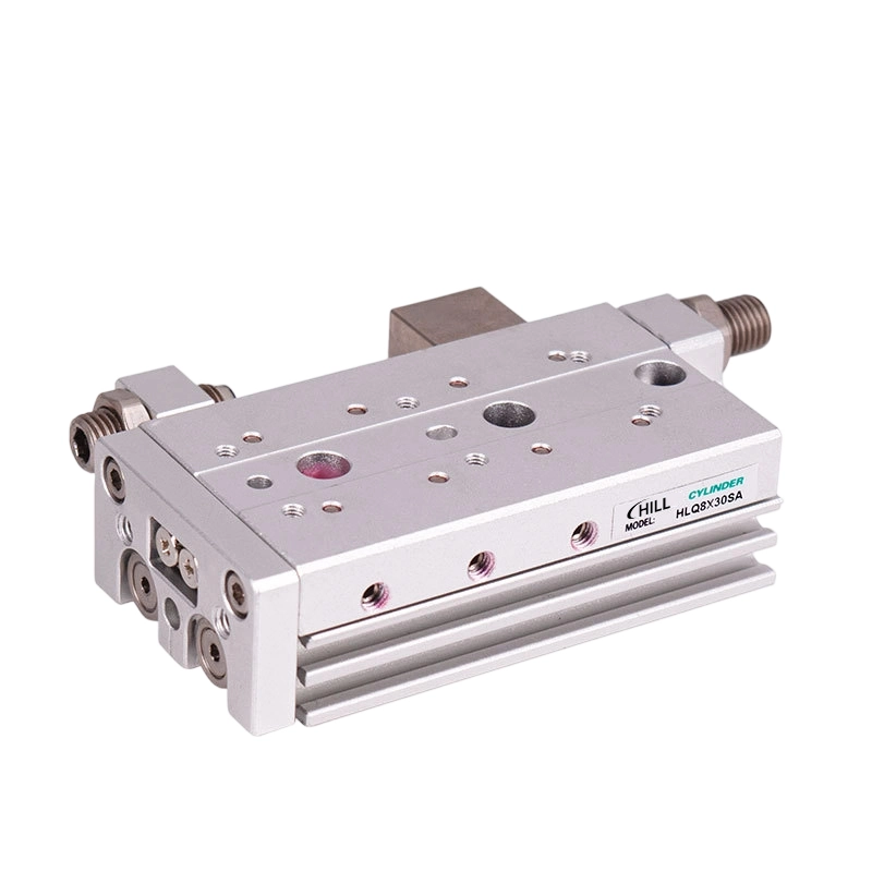
HLQ / HLQL Series
Ball-bearing guidance with standard and symmetrical layouts. Compare tool mounting, port side and the required end-stop configuration.
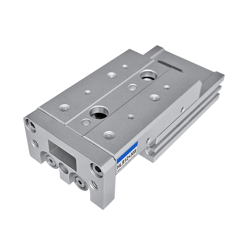
HLS / HLSL Series
Cross-roller guidance with standard and symmetrical layouts. Check the mounting arrangement, load position and stop requirements.
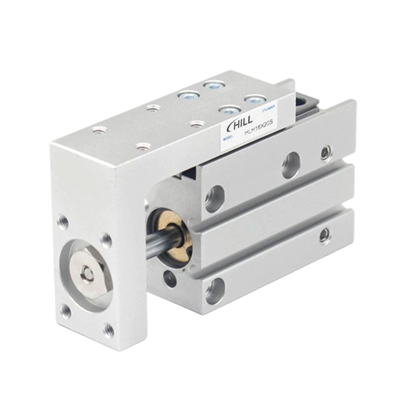
HLH Series
A miniature table for short-travel assemblies. Compare mounting direction, port access and clearance around the carried tool.
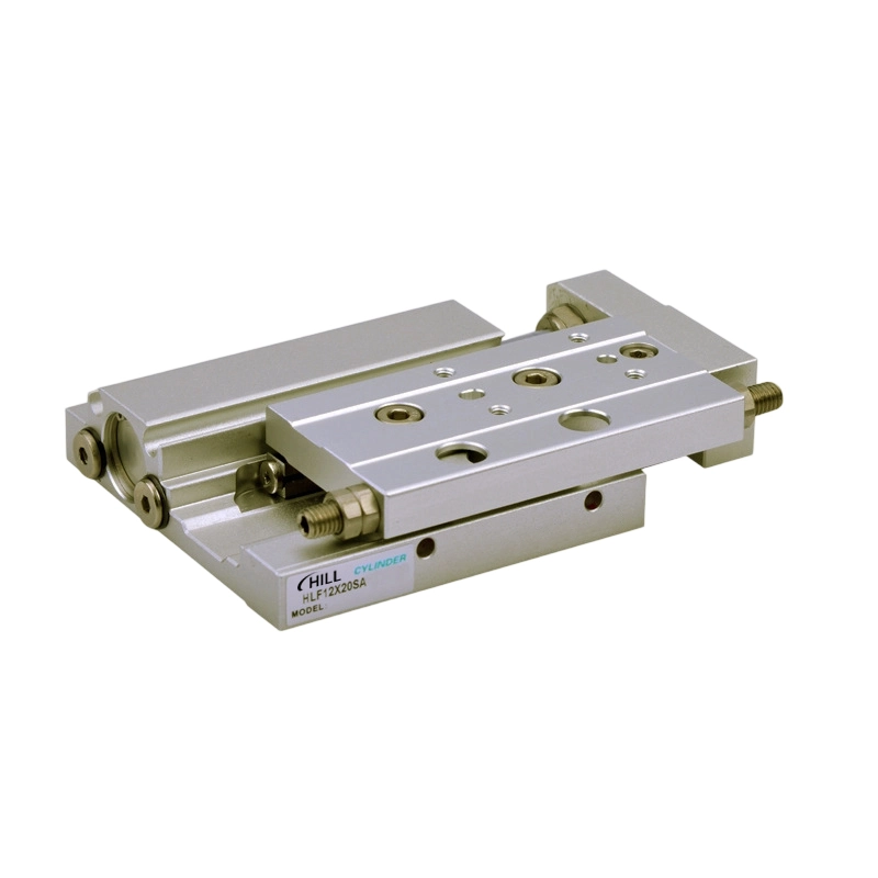
HLF Series
A thin roller-guided format. Check the low-height envelope, small metric ports and operating conditions for the selected bore.
Guide, layout
and end-stop choice.
Start with the carried tool and load position. Choose the guidance and installation layout before setting bore, stroke and end-stop options.
| Series group | Guide and layout | What to confirm |
|---|---|---|
| HLQ / HLQL Series | Ball-bearing guide; standard / symmetrical | Check port side, tool mounting and motion direction. Select the end-stop arrangement for the required end of travel. |
| HLS / HLSL Series | Cross-roller guide; standard / symmetrical | Compare the carried tool and load offset with the selected guide size. Confirm stop configuration and mounting fit. |
| HLH Series | Miniature table; multi-direction mounting | Check mounting direction and the short-travel envelope. Allow access around the tool, ports and position switches. |
| HLF Series | Thin roller-guided table | Compare the low-height envelope and small metric ports. Confirm operating pressure for the selected bore. |
B, BS and BF shock-absorber options are not listed for HLQ / HLS bore 6. Thrust acts along the travel axis; it is not an allowable payload or guide-moment rating. Provide load mass, centre-of-gravity offset, mounting orientation and motion profile for selection.
Series-specific
technical data.
Open a series for its operating conditions, end-stop codes and stroke selection. Keep bore, layout, port and sensing qualifiers with the complete model code.
HLQ / HLQL SeriesBall-bearing guide · Standard and symmetrical layouts
Scroll the table sideways to compare all variant, bore, port and stroke columns. Keyboard: focus the table area, then use the left and right arrow keys.
| Variant | Acting | Bore (mm) | Port size | Listed standard strokes (mm) | Max (mm) |
|---|---|---|---|---|---|
| HLQ / HLQL | Double acting | 6 | M5×0.8 | 10 20 30 40 50 | 50 |
| HLQ / HLQL | Double acting | 8 | M5×0.8 | 10 20 30 40 50 75 | 75 |
| HLQ / HLQL | Double acting | 12 | M5×0.8 | 10 20 30 40 50 75 100 | 100 |
| HLQ / HLQL | Double acting | 16 | M5×0.8 | 10 20 30 40 50 75 100 125 | 125 |
| HLQ / HLQL | Double acting | 20 | 1/8 | 10 20 30 40 50 75 100 125 150 | 150 |
| HLQ / HLQL | Double acting | 25 | 1/8 | 10 20 30 40 50 75 100 125 150 | 150 |
Stroke availability depends on the complete model, acting type and options. Confirm the configuration and mounting drawing before ordering.
HLS / HLSL SeriesCross-roller guide · Standard and symmetrical layouts
Scroll the table sideways to compare all variant, bore, port and stroke columns. Keyboard: focus the table area, then use the left and right arrow keys.
| Variant | Acting | Bore (mm) | Port size | Listed standard strokes (mm) | Max (mm) |
|---|---|---|---|---|---|
| HLS / HLSL | Double acting | 6 | M5×0.8 | 10 20 30 40 50 | 50 |
| HLS / HLSL | Double acting | 8 | M5×0.8 | 10 20 30 40 50 75 | 75 |
| HLS / HLSL | Double acting | 12 | M5×0.8 | 10 20 30 40 50 75 100 | 100 |
| HLS / HLSL | Double acting | 16 | M5×0.8 | 10 20 30 40 50 75 100 125 | 125 |
| HLS / HLSL | Double acting | 20 | 1/8 | 10 20 30 40 50 75 100 125 150 | 150 |
| HLS / HLSL | Double acting | 25 | 1/8 | 10 20 30 40 50 75 100 125 150 | 150 |
Stroke availability depends on the complete model, acting type and options. Confirm the configuration and mounting drawing before ordering.
HLH SeriesMiniature table · Mounting and travel
Scroll the table sideways to compare all variant, bore, port and stroke columns. Keyboard: focus the table area, then use the left and right arrow keys.
| Variant | Acting | Bore (mm) | Port size | Listed standard strokes (mm) | Max (mm) |
|---|---|---|---|---|---|
| HLH | Double acting | 6 | M5×0.8 | 5 10 15 20 25 30 | 30 |
| HLH | Double acting | 10 | M5×0.8 | 5 10 15 20 25 30 40 50 | 50 |
| HLH | Double acting | 16 | M5×0.8 | 5 10 15 20 25 30 40 50 60 | 60 |
| HLH | Double acting | 20 | M5×0.8 | 5 10 15 20 25 30 40 50 60 | 60 |
Stroke availability depends on the complete model, acting type and options. Confirm the configuration and mounting drawing before ordering.
HLF SeriesThin roller guide · Selected-bore conditions
Scroll the table sideways to compare all variant, bore, port and stroke columns. Keyboard: focus the table area, then use the left and right arrow keys.
| Variant | Acting | Bore (mm) | Port size | Listed standard strokes (mm) | Max (mm) |
|---|---|---|---|---|---|
| HLF | Double acting | 8 | M3×0.5 | 10 20 30 | 30 |
| HLF | Double acting | 12 | M3×0.5 | 10 20 30 40 50 | 50 |
| HLF | Double acting | 16 | M5×0.8 | 10 20 30 40 50 75 100 | 100 |
| HLF | Double acting | 20 | M5×0.8 | 10 20 30 40 50 75 100 | 100 |
Stroke availability depends on the complete model, acting type and options. Confirm the configuration and mounting drawing before ordering.
Integrated guidance.
Plan the carried load.
Check the carried mass, tool position and travel envelope together. Leave room for end stops, fittings and feedback around the moving table.

New machine
Provide carried mass, tool mounting, centre-of-gravity offset, travel and mounting orientation. Describe the acceleration and motion profile used by the machine.
Replacement
Record the complete model, standard or symmetrical layout, mounting drawing, ports, end-stop options and sensor details. Keep reference photos ready to share.
- Choose guide construction
- HLQ / HLQL use ball bearings; HLS / HLSL use cross rollers. HLH is a miniature table and HLF uses a thin roller-guided layout. Compare guide-load and moment requirements for the selected size.
- Include load offset
- Provide payload mass, centre of gravity, mounting orientation and acceleration profile. Cylinder thrust and bore do not define permissible guide moment.
- Set the end-stop option
- HLQ and HLS offer rubber-stopper and shock-absorber codes for both ends or a selected end. Check option availability by bore before setting the machine cycle.
- Allow port and switch access
- HLF has small metric ports that differ from larger HLQ and HLS pipe ports. Include fittings, tubing bend radius and sensor access in the installation envelope.
Check the details.
Prepare the requirement.
Use the new-machine and replacement checklists alongside the selected slide-table data.
Common questions.
How do HLQ and HLQL differ?
HLQ is the standard arrangement and HLQL is the symmetrical arrangement. Check the port side, tool mounting and motion direction against the selected drawing.
Can every HLQ or HLS bore use shock absorbers?
No. B, BS and BF shock-absorber options are not listed for bore 6. Specify whether energy absorption is needed at both ends, extension only or retraction only.
Is slide-table thrust the allowable payload?
No. Thrust acts along the travel axis. Payload depends on guide load, moment, load offset, mounting direction and motion profile. Supply these conditions for selection.
How do I specify position feedback?
Confirm a magnet-equipped model, matching switch, wiring and installation access. The listed switch families are CMSH, DMSH and EMSH; choose the electrical configuration for the control system.
Bring the slide-table
details together.
Record the full model, bore, stroke and layout. Add tool mass, centre-of-gravity offset, mounting orientation, motion profile, interfaces, quantity and schedule.
Create a slide-table briefCopy or download your component requirements.
- Series and travel
- Full code / bore / stroke / standard or symmetrical
- Tool and load
- Mass / centre-of-gravity offset / orientation / motion
- Interfaces and order
- Mounting / stops / ports / sensing / quantity / schedule