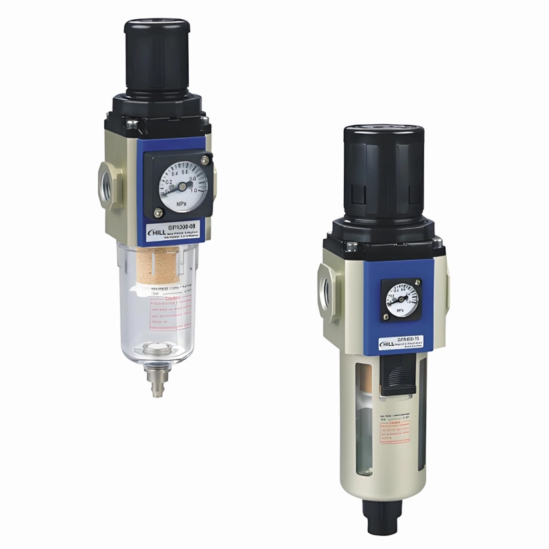
GFR Filter-Regulators
Filtration and pressure regulation in one G-platform unit. Choose the body size and port first, then specify drain, filter grade, gauge and pressure range.
- Body sizes
- GFR200 · 300 · 400 · 600
- Nominal ports
- 1/8″–1″
- Function
- Filter + regulator
Choose the body and port together.
GFR200, 300, 400 and 600 use different bowls and envelopes. Select by the required pressure and flow conditions as well as the connection size.
| Parameter | Catalog reference |
|---|---|
| Working medium | Air |
| Filter grade | 40 μm standard; 5 μm option |
| Pressure adjustment: differential / automatic drain | 0.15–0.9 MPa |
| Pressure adjustment: manual drain | 0.05–0.9 MPa |
| Low-pressure L option | Maximum adjustable pressure 0.4 MPa |
| Maximum operating pressure | 1.0 MPa |
| Proof pressure | 1.5 MPa |
| Temperature | −5 to +70 °C; non-freezing |
| Thread options | PT standard; G or NPT option |
The drain configuration changes the lower adjustment limit. The low-pressure option has a separate upper limit.
| Model | Nominal port | Bowl capacity | Reference weight |
|---|---|---|---|
| GFR200-06 | 1/8″ | 10 cm³ | 220 g |
| GFR200-08 | 1/4″ | 10 cm³ | 220 g |
| GFR300-08 | 1/4″ | 40 cm³ | 500 g |
| GFR300-10 | 3/8″ | 40 cm³ | 500 g |
| GFR300-15 | 1/2″ | 40 cm³ | 500 g |
| GFR400-10 | 3/8″ | 80 cm³ | 1030 g |
| GFR400-15 | 1/2″ | 80 cm³ | 1030 g |
| GFR600-20 | 3/4″ | 230 cm³ | 2400 g |
| GFR600-25 | 1″ | 230 cm³ | 2400 g |
Capacity and weight follow the body groups in the cited table. Confirm the weight of the selected drain, gauge and accessory assembly.
Scroll the table horizontally to compare all columns.
Specify the drain and pressure options.
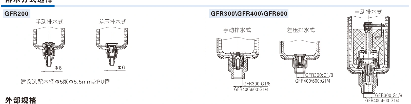
Drain type, pressure range and gauge are separate order fields. Automatic drain is listed for GFR300/400/600; it is not listed for GFR200 in this reference.
Drain selection
| Body | Blank code | M code | A code |
|---|---|---|---|
| GFR200 | Differential-pressure drain | Manual drain | Not listed |
| GFR300 / 400 / 600 | Differential-pressure drain | Manual drain | Automatic drain |
Drain connections and bowl arrangements differ. Check the drain reference before laying out the discharge line.
Scroll the table horizontally to compare all columns.
Other order fields
| Field | Catalog-listed options |
|---|---|
| Pressure range | Blank: standard; L: low pressure, maximum adjustment 0.4 MPa |
| Bracket | Blank: with bracket; J: without bracket |
| Gauge supplied | Blank: with gauge; N: without gauge |
| Gauge form | F: square; C: round |
| Scale units | 1: MPa; 2: psi; 3: bar |
| Filter grade | Blank: 40 μm; W: 5 μm |
| Thread | Blank: PT; G: G; T: NPT |
| Reverse-flow valve | Blank: without; K: with reverse-flow valve |
Specify required fields in the full catalog ordering sequence. Availability of the complete configuration is confirmed with the selected product.
Drain arrangements by body size
Read the original configuration sequence

Reserve the complete service envelope.
Check the bowl, adjustment knob, gauge and drain clearance together. All linear dimensions below are in mm; drawing symbols refer to the accompanying dimensioned outline.
| Model | A | B | C | D | Port P | Drain Q |
|---|---|---|---|---|---|---|
| GFR300-08 | 60 | 72 | 225.5 | M40 × 1.5 | PT1/4 | G1/8 |
| GFR300-10 | 60 | 72 | 225.5 | M40 × 1.5 | PT3/8 | G1/8 |
| GFR300-15 | 60 | 72 | 225.5 | M40 × 1.5 | PT1/2 | G1/8 |
| GFR400-10 | 80 | 90 | 270.5 | M55 × 2.0 | PT3/8 | G1/4 |
| GFR400-15 | 80 | 90 | 270.5 | M55 × 2.0 | PT1/2 | G1/4 |
P follows the PT-thread drawing. A different thread option must be matched to the selected full code. GFR200 and GFR600 have separately dimensioned outlines.
Scroll the table horizontally to compare all columns.
Body and connection dimensions

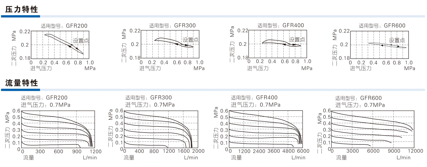
Pressure and flow characteristics
Technical reference: AirTAC G-series GFR catalog, printed pp.241–242. Confirm the offered full configuration and current drawing. Other FRL platforms require their own matched data.
Check flow at the required outlet pressure.
Port size alone is not a flow rating. The catalog curves show outlet pressure changing with flow for each GFR body under the stated inlet condition.
- Flow and pressure
- Provide inlet pressure, required outlet pressure and air demand. Use the selected-body curve and account for pressure drop through the complete air system.
- Condensate discharge
- Choose manual, differential-pressure or automatic drainage for the installation. Confirm drain routing and access for bowl inspection and service.
- Gauge and mounting
- Confirm gauge presence, shape and scale, bracket requirement, thread type and readable orientation. Reserve room around the knob and bowl.
- Function and combination
- GFR combines filtration and regulation. If lubrication or a larger preparation assembly is required, specify it separately rather than assuming it is included.
Specify the air condition and complete unit.
Include the GFR body, port and thread, inlet/outlet pressures, required flow, drain type, filtration, gauge, bracket and quantity. Add available mounting and bowl-service space.
The brief tool creates text on your device to copy or download. It does not send an online enquiry.
Can I use AFR/BFR dimensions for GFR?
Use the GFR drawing for the G platform and the exact selected body. AFR/BFR values and dimensions must not be substituted.
Does a 1/2-inch connection identify one body size?
No. This reference lists 1/2-inch ports on both GFR300-15 and GFR400-15. Their body dimensions, bowl capacities and flow curves differ.