Fluid control
valves.
Valve options for process-fluid circuits and compressed-air pulse duty. Start with the medium, temperature and pressure difference, then match the seals, actuation and connections to the selected model.

Six valve platforms.
Start with the service.
Compare process duty and control method before matching the complete model. The photos show representative configurations; materials and operating limits depend on the selected version.
2J Series
Air-operated angle-seat platform. Match the medium and seals, then confirm actuator size and the separate control-air supply.

US Series
Steam-solenoid platform. Match the steam and condensate conditions, pressure differential, selected coil and installation.

2W Series
General fluid solenoid platform. Confirm the operating principle, minimum differential pressure, body and seals for the exact model.

2Q Series
Air-operated fluid valve. Specify process pressure and the separate control-air supply before matching the complete model.

Q22HD Series
Compact air-operated process valve. Compare the port marking, Kv and mounting envelope with the selected-model drawing.

DMF Series
Clean compressed-air pulse control. Match the structure, type-specific working pressure and manifold or control connections.
Match the duty.
Separate the control supply.
Start with the actual medium and process conditions. Then compare the actuation method, control supply and installation interface for the selected series.
| Series group | Actuation and service | What to confirm |
|---|---|---|
| 2J Series | Pneumatic angle-seat valve | Specify the medium, process pressure and temperature, required flow, body and seals. Select the actuator and available control air together. |
| US Series | Steam solenoid valve | Include steam and condensate conditions, inlet and outlet pressure, start-up differential pressure, selected coil and installation orientation. |
| 2W Series | General fluid solenoid valve | Confirm the operating principle and minimum differential pressure for the exact size and construction. Match the body and seal to the actual medium. |
| 2Q Series | Air-operated fluid valve | Keep process-fluid pressure separate from the pneumatic control-air supply. Confirm the seal, normal state and installation space for the complete valve. |
| Q22HD Series | Compact air-operated process valve | Compare the Kv reference and literal port marking with the mating pipe specification. Confirm control air, materials and mounting dimensions. |
| DMF Series | Intermittent compressed-air pulse valve | Identify the Y, T or P structure, working air pressure, pulse control and manifold layout. The illustrated sample does not define every structure or coil option. |
Process pressure and actuator control air are separate selection inputs. A matching port size or coefficient value does not establish the same flow, service suitability or replacement fit.
Series data.
Check the complete model.
Compare the model and operating tables for the same series. Keep Cv and Kv distinct, and confirm the selected configuration against the actual process conditions.
2J SeriesAngle-seat model, actuator and operating references
Scroll sideways to read every column. Keyboard: focus the table area, then use the left and right arrow keys.
| Model | Orifice (mm) | Port | Kv (m³/h) | Actuator diameter |
|---|---|---|---|---|
| 2JS150-15 | 15 | G 1/2″ | 4.7 | 50mm |
| 2JS200-20 | 20 | G 3/4″ | 9.5 | 50mm |
| 2JS250-25 | 25 | G 1″ | 19 | 63mm |
| 2JS320-32 | 32 | G 1-1/4″ | 27 | 63mm |
| 2JS400-40 | 40 | G 1-1/2″ | 46 | 63mm |
| 2JS500-50 | 50 | G 2″ | 72 | 90mm |
| Parameter | Configuration |
|---|---|
| Working pressure | 0–16 bar |
| Fluid temperature | −20 to +180°C |
| Seat seal | PTFE |
| Stem seal options | PTFE / FKM |
| Actuator | Polyamide; single- or double-acting options |
Check fluid compatibility, control pressure and actuator size for the chosen valve. Maximum pressure and temperature values are not a combined service approval.
Confirm the body grade, actuator configuration and complete-model drawing for the actual medium. The range photograph does not establish a material grade or installation dimension.
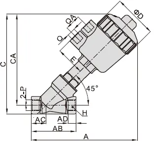
Check the selected model drawing.
The outline shows dimension letters rather than a complete-model dimension table. Confirm the selected valve drawing, connection standard and installation clearances.
Open original outlineUS SeriesSteam-solenoid model and configuration references
Scroll sideways to read every column. Keyboard: focus the table area, then use the left and right arrow keys.
| Model | Port | Cv |
|---|---|---|
| US-15 | G 1/2″ | 4.8 |
| US-20 | G 3/4″ | 7.6 |
| US-25 | G 1″ | 12 |
| US-35 | G 1-1/4″ | 22 |
| US-40 | G 1-1/2″ | 29 |
| US-50 | G 2″ | 48 |
Confirm the required operating differential pressure and installation orientation for the exact model.
| Parameter | Configuration |
|---|---|
| Maximum pressure | 1.6 MPa |
| Media temperature | −5 to 200°C |
| Body / seal | Forged brass / PTFE |
| Piston | Stainless steel |
| Coil voltage options | AC 380 / 220 / 36 V; DC 24 V |
Confirm the exact coil, ambient conditions, duty and suitability for the process temperature.
The listed construction is a source configuration; confirm the body and selected coil for the complete model. Maximum pressure and temperature values do not establish a combined process-service approval.
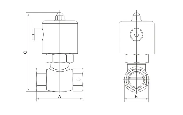
Check the selected model drawing.
The outline shows dimension letters rather than a complete-model dimension table. Confirm the selected valve drawing, connection standard and installation clearances.
Open original outline2W SeriesModel flow, body and standard seal references
Scroll sideways to read every column. Keyboard: focus the table area, then use the left and right arrow keys.
| Model | Port | Orifice (mm) | Cv |
|---|---|---|---|
| 2W-025-08 | 1/4″ | 2.5 | 0.23 |
| 2W-040-10 | 3/8″ | 4.0 | 0.60 |
| 2W-160-15 | 1/2″ | 16.0 | 4.8 |
| 2W-200-20 | 3/4″ | 20.0 | 7.6 |
| 2W-250-25 | 1″ | 25.0 | 12.0 |
| 2W-500-50 | 2″ | 50.0 | 48.0 |
Confirm operating principle and minimum differential pressure for the exact size and construction; do not infer zero-pressure operation from the series name.
| Parameter | Options |
|---|---|
| Body | Brass / stainless steel |
| Standard seal | NBR |
| Fluid temperature with NBR | −5 to 80°C |
| Armature | Stainless steel |
| Coil options | AC 220 V / DC 24 V |
Check the medium, seal and pressure limits for the selected model. A seal change alone does not approve every body and coil for higher temperature.
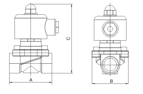
Check the selected model drawing.
This source outline covers related valve variants. Confirm the complete 2W model drawing and connection dimensions; the reference does not establish one set of dimensions for every size.
Open original outline2Q SeriesProcess-valve models and separate control-air supply
Scroll sideways to read every column. Keyboard: focus the table area, then use the left and right arrow keys.
| Model | Port | Orifice (mm) | Cv | Control-air pressure |
|---|---|---|---|---|
| 2Q160-15 | 1/2″ | 16 | 4.8 | 0.3 ~ 0.6 MPa |
| 2Q200-20 | 3/4″ | 20 | 12 | 0.3 ~ 0.6 MPa |
| 2Q250-25 | 1″ | 25 | 18 | 0.3 ~ 0.6 MPa |
| 2Q350-35 | 1-1/4″ | 35 | 24 | 0.3 ~ 0.6 MPa |
| 2Q400-40 | 1-1/2″ | 40 | 29 | 0.3 ~ 0.6 MPa |
| 2Q500-50 | 2″ | 50 | 48 | 0.3 ~ 0.6 MPa |
| Parameter | Configuration |
|---|---|
| Working pressure | 0–0.7 MPa |
| Fluid temperature | −5 to 100°C |
| Control-air pressure | 0.3–0.6 MPa |
| Body | Brass |
| Seal options | NBR / EPDM / FKM |
| Actuator | Aluminium |
Keep fluid and control-air pressure separate. Validate the seal option for the actual fluid and temperature.
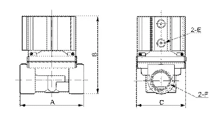
Check the selected model drawing.
This small source outline is a visual reference. Confirm dimensions and control-air connections on the selected-model drawing before installation.
Open original outlineQ22HD SeriesPort marking, Kv and operating references
Scroll sideways to read every column. Keyboard: focus the table area, then use the left and right arrow keys.
| Model | Port marking | Nominal diameter | Kv |
|---|---|---|---|
| Q22HD-15 | ZG 1/2″ | 15mm | 4 |
| Q22HD-20 | ZG 3/4″ | 20mm | 5 |
| Q22HD-25 | ZG 1″ | 25mm | 10 |
| Q22HD-35 | ZG 1-1/4″ | 35mm | 25 |
| Q22HD-40 | ZG 1-1/2″ | 40mm | 25 |
| Q22HD-50 | ZG 2″ | 50mm | 40 |
Confirm the connection standard represented by the port marking and the mating pipe specification.
| Parameter | Configuration |
|---|---|
| Fluid pressure | 0–1.0 MPa |
| Fluid temperature | −5 to 80°C |
| Body | Brass |
| Piston | Aluminium / brass |
| Seal options | NBR / FKM |
Provide control-air conditions and complete model. Higher-temperature seal options require model-specific confirmation.
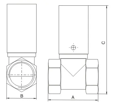
Check the selected model drawing.
The outline shows dimension letters rather than a complete-model dimension table. Confirm the selected valve drawing, connection standard and installation clearances.
Open original outlineDMF SeriesStructure-specific pulse duty and material references
Scroll sideways to read every column. Keyboard: focus the table area, then use the left and right arrow keys.
| Type | Structure | Working pressure | Size options |
|---|---|---|---|
| DMF-Y (Embedded) | Manifold Mount | 0.2 ~ 0.6 MPa | 1″, 1.5″, 2″, 3″ |
| DMF-T (Inline) | Straight Through | 0.3 ~ 0.6 MPa | 1.5″, 2″, 2.5″, 3″ |
| DMF-P (Piston) | Piston Type | 0.2 ~ 0.6 MPa | – |
Confirm the full code, manifold dimensions and control connection. A dash for DMF-P does not define a size range.
| Parameter | Configuration |
|---|---|
| Medium | Clean air |
| Temperature | −25 to 60°C |
| Body | ADC12 aluminium |
| Diaphragm options | Nitrile / FKM |
| Armature | 430FR stainless steel |
| Spring | 321 stainless steel |
Use the structure-specific working pressures when selecting DMF-Y, DMF-T or DMF-P.
Diaphragm material options apply only to configurations fitted with that component. Confirm the selected Y, T or P structure and its applicable internal materials.
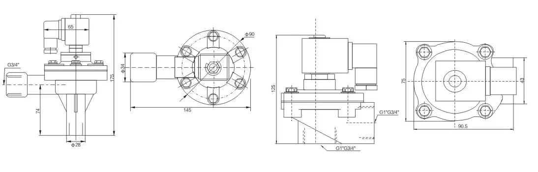
Check the selected model drawing.
These two outline examples are not assigned to DMF-Y, DMF-T or DMF-P models. Confirm the complete model and its drawing before using any shown dimensions or connections.
Open original outlineDefine the process.
Plan the control supply.
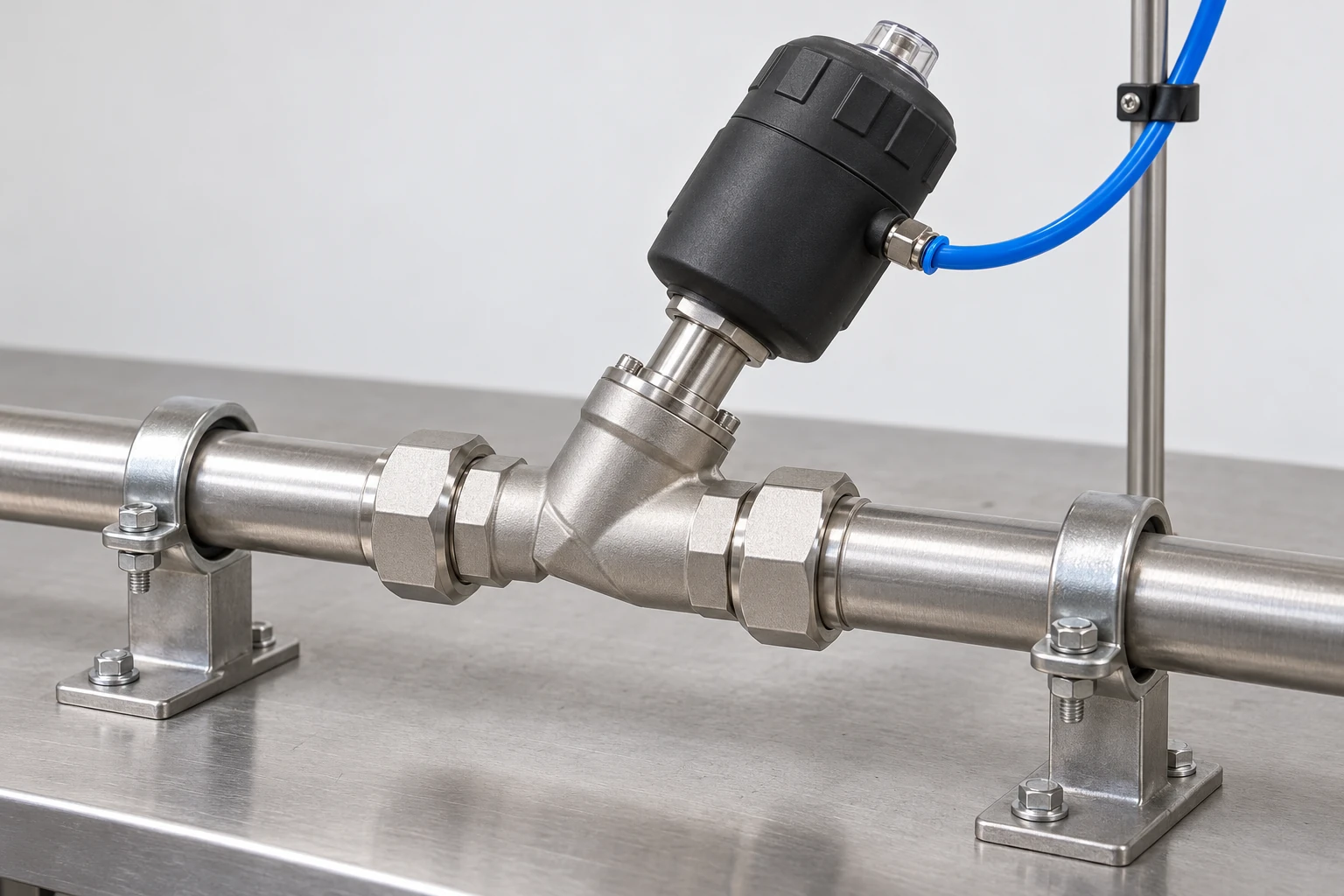
Keep the process line and actuation supply separate. Check the selected valve against the actual medium, temperature, pressure difference and installation space.
New machine
Provide medium and composition, normal and peak temperature, inlet and outlet pressures, flow and acceptable pressure drop. Add normal state, electrical or pneumatic control supply, connection standard and installation space.
Replacement
Record the complete valve code, material and seal option if known, body and coil labels, pipe standard and selected-model drawing. Include actual process conditions and electrical or pneumatic control details.
- Describe the process medium
- Identify fluid, concentration, contamination and viscosity where relevant. Include normal and cleaning conditions so body, seat and stem seals can be checked.
- Give inlet and outlet pressures
- State minimum and maximum inlet pressure, downstream back-pressure and differential pressure at start-up and during operation. For air-operated valves, give the separate control-air supply.
- Separate process and ambient temperature
- Provide normal and peak fluid temperature, exposure time and ambient temperature near the actuator or coil. Check the exact seal and coil option.
- Define actuation and normal state
- Choose electrical or pneumatic control and specify normally closed/open behaviour. Include available control supply and any spring-return requirement.
- Match connection and flow
- Confirm pipe size, actual thread standard, flow and acceptable pressure drop. Cv and Kv use different reference units; retain the stated coefficient when comparing models.
- Define the pulse circuit
- For DMF selection, specify structure, port, working air pressure, electrical control and manifold layout. Pulse valves serve compressed-air discharge circuits.
Selection resources.
Questions before ordering.
Use the checklists with the selected valve data and model drawing. Keep process conditions and the control supply in the same requirement.
Common questions.
Which groups should I compare for steam?
Start with 2J angle-seat and US steam-solenoid groups. Provide steam pressure, temperature, condensate conditions, required flow and switching duty. Confirm the exact body, seal, actuator or coil configuration.
Does every 2W valve operate at zero differential pressure?
The operating principle varies with size and construction. Confirm the minimum differential pressure and exact model before using a 2W valve on a gravity-fed or low-pressure line.
Why do air-operated valves need two pressure values?
The process circuit and pneumatic actuator are separate. Give fluid inlet/outlet pressures and available control-air pressure so valve and actuator can be selected together.
Can a different seal make any valve suitable for steam or chemicals?
The body, internal materials, actuator or coil, temperature and pressure must also suit the actual medium and concentration.
How should I compare Cv and Kv?
They are flow coefficients using different reference units. The 2J and Q22HD tables use Kv; several other series use Cv. Use the correct coefficient definition and process conditions for calculations.
What belongs in a fluid-valve requirement brief?
Include medium/composition, normal/peak temperature, inlet/outlet pressures, flow, connection size/standard, normal state, actuation and available electrical or pneumatic control supply.
Bring the process
details together.
Start with the medium, temperature and inlet and outlet pressures. Add the required flow, normal state, electrical or pneumatic control supply, pipe interface and complete model reference.
Create a fluid-valve briefCopy or download your component requirements.
- Medium and temperature
- Composition / normal and peak temperature / cleaning conditions
- Pressure and flow
- Inlet and outlet / start-up differential / required flow / acceptable pressure drop
- Control and connections
- Electrical or pneumatic supply / normal state / pipe standard / selected model drawing
- Order details
- Quantity / schedule / project destination, if relevant