
A Series FRL Units
Classic modular air preparation with separate filters, regulators and lubricators, plus two-unit and three-unit combinations. Choose only the functions required by the downstream equipment.
A Series FRL Units
Selection overview.
Build a point-of-use air preparation assembly from a filter, regulator and optional lubricator. The classic A platform offers individual AF, AW, AR and AL components, plus AC assemblies with either integrated or separate filtration and regulation.
Confirm the product-specific operating limits and dimensions for the selected series before use.
Series and configurations.
Use the series as a starting point. Provide the complete size and configuration in your requirement brief.
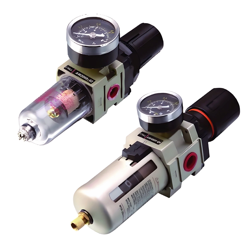


Compare the series.
Review the construction, function and interfaces before narrowing the model.
| Series | Function | Selection focus |
|---|---|---|
| AF Series | Separate air filter | Drainage, element and bowl access |
| AW Series | Filter + regulator | Compact filtration and pressure adjustment |
| AR Series | Pressure regulator | Outlet pressure and gauge connection |
| AL Series | Air-line lubricator | Oil requirement and bowl capacity |
| AC Two-Unit | AW + AL | Integrated filtration/regulation with lubrication |
| AC Three-Unit | AF + AR + AL | Separate components for servicing and layout |
Model-specific technical data.
Open the relevant model group to review its listed specification. Options and operating limits apply to the displayed series and configuration.
Classic A platform – operating values by function
| Series | Maximum pressure | Proof pressure | Temperature | Filtration | Regulation range |
|---|---|---|---|---|---|
| AF Series | 1.0 Mpa | 1.5 Mpa | 5 ~ 60°C | 5 μm | – |
| AW Series | 1.0 Mpa | 1.5 Mpa | 5 ~ 60°C | 5 μm | 0.05 ~ 0.85 Mpa |
| AR Series | 1.0 Mpa | 1.5 Mpa | 5 ~ 60°C | – | 0.05~0.85 Mpa |
| AL Series | 1.0 Mpa | 1.5 Mpa | 5 ~ 60°C | – | – |
| AC Two-Unit | 1.0 Mpa | 1.5 Mpa | 5 ~ 60°C | 5 μm | – |
| AC Three-Unit | 1.0 Mpa | 1.5 Mpa | 5 ~ 60°C | 5 μm | – |
For compressed air. Prevent freezing. Proof pressure is a test value; select the complete assembly for its lowest allowable working limit.
AF Series – model selection
| Model | Manual drain code | Auto drain code | Rated flow (L/min) | Port size (Rc unless metric) | Bowl capacity (cm³) | Weight (kg) |
|---|---|---|---|---|---|---|
| AF1000-M5 | Blank | D | 110 | M5 x 0.8 | 4 | 0.07 |
| AF2000-02 | Blank | D | 750 | 1/4″ | 15 | 0.19 |
| AF3000-02 | Blank | D | 1500 | 1/4″ | 20 | 0.29 |
| AF3000-03 | Blank | D | 1500 | 3/8″ | 20 | 0.29 |
| AF4000-03 | Blank | D | 4000 | 3/8″ | 45 | 0.55 |
| AF4000-04 | Blank | D | 4000 | 1/2″ | 45 | 0.55 |
| AF4000-06 | Blank | D | 6000 | 3/4″ | 45 | 0.58 |
| AF5000-06 | Blank | D | 7000 | 3/4″ | 130 | 1.08 |
| AF5000-10 | Blank | D | 7000 | 1″ | 130 | 1.08 |
Confirm the exact port thread and mounting dimensions before selection. Check rated-flow conditions and pressure-drop curves at the actual operating point.
AW Series – model selection
| Model | Rated Flow (L/min) | Port Size (Rc) | Gauge Port (Rc) | Weight (kg) |
|---|---|---|---|---|
| AW1000-M5 | 100 | M5 x 0.8 | 1/16 | 0.09 |
| AW2000-02 | 550 | 1/4″ | 1/8 | 0.36 |
| AW3000-02 | 2000 | 1/4 | 1/8 | 0.56 |
| AW3000-03 | 2000 | 3/8 | 1/8 | 0.56 |
| AW4000-03 | 4000 | 3/8 | 1/4 | 1.15 |
| AW4000-04 | 4000 | 1/2 | 1/4 | 1.15 |
| AW4000-06 | 4500 | 3/4 | 1/4 | 1.21 |
| AW5000-06 | 5000 | 3/4 | 1/4 | – |
| AW5000-10 | 5000 | 1″ | 1/4 | – |
Confirm the exact port thread and mounting dimensions before selection. Check rated-flow conditions and pressure-drop curves at the actual operating point.
AR Series – model selection
| Model | Rated Flow (L/min) | Port Size (Rc) | Gauge Port (Rc) | Weight (kg) |
|---|---|---|---|---|
| AR1000-M5 | 100 | M5 x 0.8 | 1/16 | 0.08 |
| AR2000-02 | 550 | 1/4″ | 1/8 | 0.27 |
| AR3000-02 | 2500 | 1/4″ | 1/8 | 0.41 |
| AR3000-03 | 2500 | 3/8″ | 1/8 | 0.41 |
| AR4000-03 | 6000 | 3/8″ | 1/4 | 0.84 |
| AR4000-04 | 6000 | 1/2″ | 1/4 | 0.84 |
| AR4000-06 | 6000 | 3/4″ | 1/4 | 0.94 |
| AR5000-06 | 8000 | 3/4″ | 1/4 | 1.19 |
| AR5000-10 | 8000 | 1″ | 1/4 | 1.19 |
Confirm the exact port thread and mounting dimensions before selection. Check rated-flow conditions and pressure-drop curves at the actual operating point.
AL Series – model selection
| Model | Rated Flow (L/min) | Port Size (Rc) | Bowl Cap. (cm³) | Weight (kg) |
|---|---|---|---|---|
| AL1000-M5 | 95 | M5 x 0.8 | 7 | 0.07 |
| AL2000-02 | 800 | 1/4″ | 25 | 0.22 |
| AL3000-02 | 1700 | 1/4″ | 50 | 0.30 |
| AL3000-03 | 1700 | 3/8″ | 50 | 0.30 |
| AL4000-03 | 5000 | 3/8″ | 130 | 0.56 |
| AL4000-04 | 5000 | 1/2″ | 130 | 0.56 |
| AL4000-06 | 6300 | 3/4″ | 130 | 0.58 |
| AL5000-06 | 7000 | 3/4″ | 130 | 1.08 |
| AL5000-10 | 7000 | 1″ | 130 | 1.08 |
Confirm the exact port thread and mounting dimensions before selection. Check rated-flow conditions and pressure-drop curves at the actual operating point.
AC Two-Unit – model selection
| Model | Combination (Filter/Reg + Lub) | Rated Flow (L/min) | Port Size (Rc) | Gauge Port (Rc) | Weight (kg) |
|---|---|---|---|---|---|
| AC1010-M5 | AW1000 + AL1000 | 90 | M5 x 0.8 | 1/16 | 0.22 |
| AC2010-02 | AW2000 + AL2000 | 500 | 1/4″ | 1/8 | 0.66 |
| AC3010-02 | AW3000 + AL3000 | 1700 | 1/4″ | 1/8 | 0.98 |
| AC3010-03 | AW3000 + AL3000 | 1700 | 3/8″ | 1/8 | 0.98 |
| AC4010-03 | AW4000 + AL4000 | 3000 | 3/8″ | 1/4 | 1.93 |
| AC4010-04 | AW4000 + AL4000 | 3000 | 1/2″ | 1/4 | 1.93 |
| AC4010-06 | AW4000 + AL4000 | 3000 | 3/4″ | 1/4 | 1.99 |
| AC5010-06 | AW5000 + AL5000 | 4000 | 3/4″ | 1/4 | – |
| AC5010-10 | AW5000 + AL5000 | 4000 | 1″ | 1/4 | – |
Confirm the exact port thread and mounting dimensions before selection. Check rated-flow conditions and pressure-drop curves at the actual operating point.
AC Three-Unit – model selection
| Model | Combination (F + R + L) | Rated Flow (L/min) | Port Size (Rc) | Gauge Port (Rc) | Weight (kg) |
|---|---|---|---|---|---|
| AC1000-M5 | AF1000+AR1000+AL1000 | 90 | M5 x 0.8 | 1/16 | 0.26 |
| AC2000-02 | AF2000+AR2000+AL2000 | 500 | 1/4″ | 1/8 | 0.74 |
| AC3000-02 | AF3000+AR3000+AL3000 | 2000 | 1/4″ | 1/8 | 1.18 |
| AC3000-03 | AF3000+AR3000+AL3000 | 2000 | 3/8″ | 1/8 | 1.18 |
| AC4000-03 | AF4000+AR4000+AL4000 | 4000 | 3/8″ | 1/4 | 2.14 |
| AC4000-04 | AF4000+AR4000+AL4000 | 4000 | 1/2″ | 1/4 | 2.14 |
| AC4000-06 | AF4000+AR4000+AL4000 | 4500 | 3/4″ | 1/4 | 2.47 |
| AC5000-06 | AF5000+AR5000+AL5000 | 5000 | 3/4″ | 1/4 | 3.82 |
| AC5000-10 | AF5000+AR5000+AL5000 | 5000 | 1″ | 1/4 | 3.82 |
Confirm the exact port thread and mounting dimensions before selection. Check rated-flow conditions and pressure-drop curves at the actual operating point.
Specify the details
that affect fit and function.
Choose the treatment functions
Use AF for filtration, AR for pressure adjustment or AW when both are needed in one body. Add AL only where downstream equipment requires oil-mist lubrication.
Size for the operating point
Compare the model’s port, rated flow and available supply pressure. Check flow against allowable pressure drop; a larger port alone does not establish adequate flow.
Plan drainage and service access
Allow access below the bowl for drainage and servicing. Specify the drain and bowl protection, keeping the bowl upright and accessible.
Identify the exact platform
Include the full code and thread. Similar AF, AR and AC names occur on other platforms; verify mounting, port positions and gauge connections before replacement.
Include in your requirement
- Required air flow
- Port size and thread
- Inlet and regulated pressure
- Filtration grade
- Drain arrangement
- Lubrication requirement
- Available installation space
Select flow at the required working pressure and allowable pressure drop. Confirm drain type, bowl protection and mounting dimensions for the chosen model. Replacement dimensions and accessories require model-specific confirmation.
Questions about a series frl units.
How do the AC combinations differ?
The two-unit AC…10 uses AW and AL. The three-unit AC…00 uses separate AF, AR and AL components. Select by function, space and required flow.
Does every circuit need a lubricator?
Include a lubricator only when downstream equipment specifies air-line lubrication. Check that the components and process are suitable for oil mist.
Is proof pressure an operating limit?
No. Proof pressure is a test value. Use the maximum working pressure and required regulated pressure for operation, and check every component.
Does a matching name confirm a replacement?
Match the full code, thread, port centres, bracket holes, gauge position and bowl clearance. The series name alone does not confirm mechanical interchangeability.
Related categories.
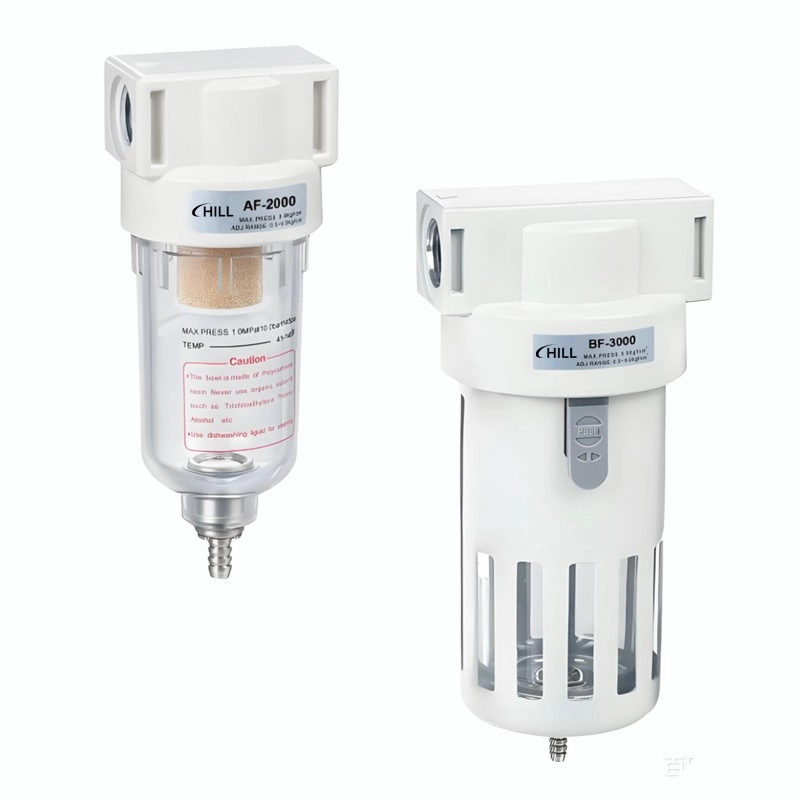
A/B Series FRL Units
A/B platform filters, regulators, lubricators and combination units for general pneumatic circuits. Compare the body size and connection layout with the installation.
Review series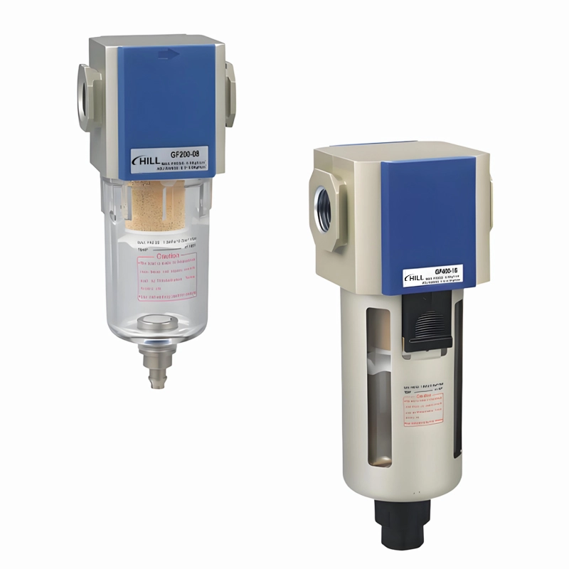
G Series FRL Units
G-platform air preparation components covering filtration, pressure regulation and lubrication. Compare standalone units and combinations by flow, port size and drain configuration.
Review seriesPrepare a a series frl units brief.
Add the preferred series, size, interfaces, quantity and your operating requirements.