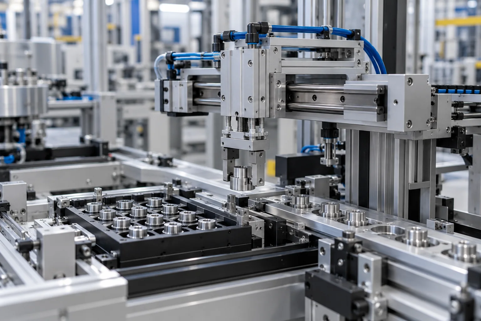
Automation & assembly.
Start with the moving load.
Coordinate the motion, guide, fixture, valve and sensing interfaces for transfer and assembly tasks before selecting the pneumatic components.
Transfer and assembly · AI-generated concept.
Illustrative context, not a customer installation.
Choose the actuator
with the mechanism.
A transfer axis, a guided plate and a fixture clamp place different loads on a pneumatic actuator. The mass, overhang, direction and mounting position affect the arrangement to review. A common stroke or bore does not establish mechanical interchangeability.
Guided cylinders and slide tables provide different moving interfaces. Match the selected construction to the tooling and circuit rather than using a generic scene as an installation drawing. JEMWON supplies its own fittings and tubing alongside sourced pneumatic components supported by procurement and project experience.
Review the complete motion interface.
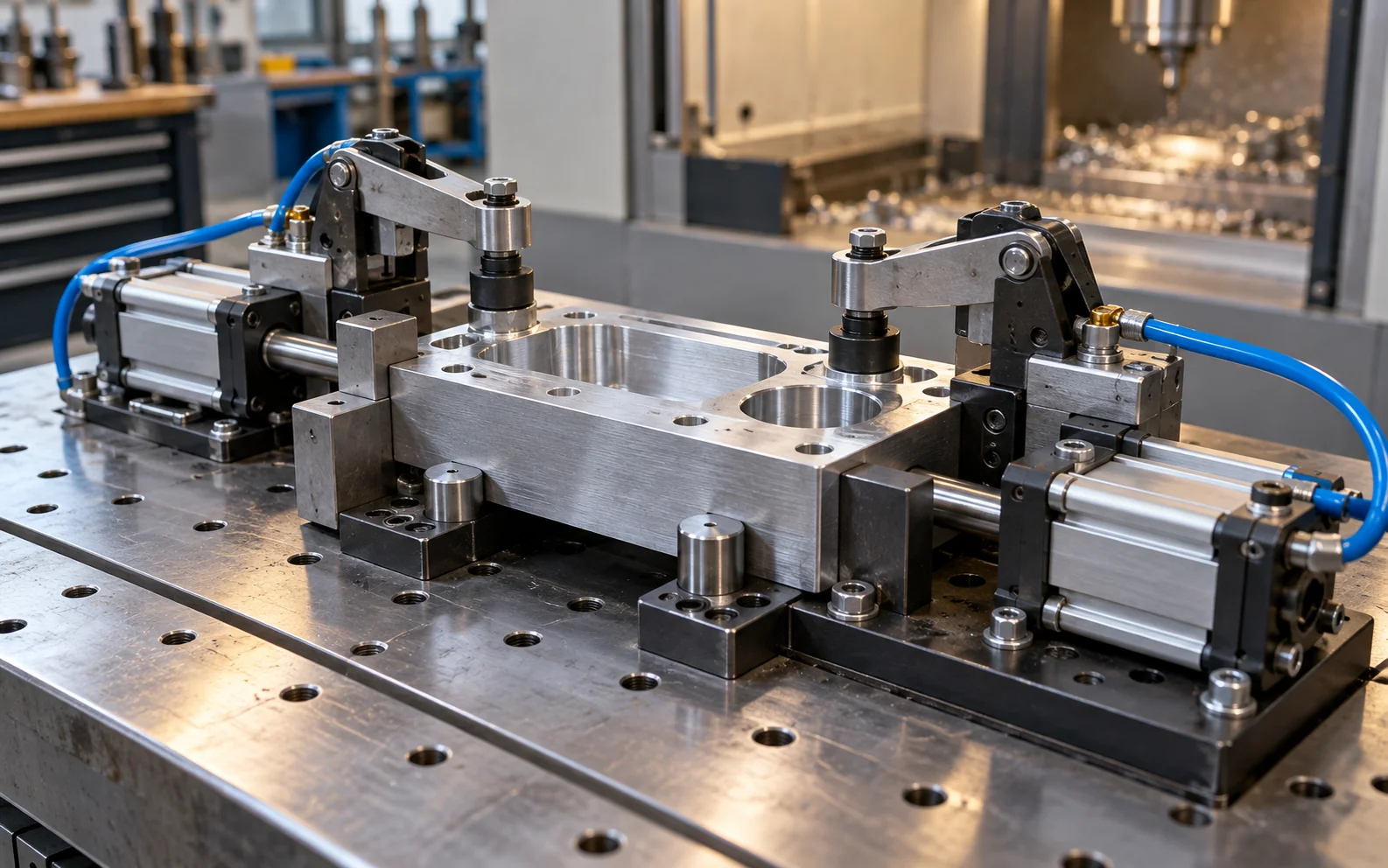
Moving load and overhang
Provide the payload, tooling mass, centre of gravity, overhang and orientation. Show acceleration or impact conditions where relevant. Review the permissible load and moments for the selected guide and size; a catalog family name does not establish an allowable value.
Guide and mounting format
Identify whether the tooling mounts to a guided end plate, moving table or separate external guide. Provide mounting faces, hole patterns, travel envelope and stops. Keep side loads and moments within the selected component’s documented limits.
Valve states and position signals
Provide the pneumatic schematic, intended operating sequence, valve function, normal state and coil supply. Specify the required sensor type, connector, mounting position and controller interface; the presence of a groove or magnet option does not confirm sensor compatibility.
Tube movement and service access
Show fixed and moving tube runs, bend space, connector directions and the full travel range. Keep the planned route clear of pinch and abrasion points. Confirm tube grade and size for the actual movement, environment and operating conditions.
Holding, stopping and stored energy
Define the required behaviour during loss of air or control power and at machine access. This general component guide does not validate load holding, safe clamping, emergency stopping or isolation. Those functions require the actual machine design, risk assessment and appropriate components and documentation.
Compare the moving interfaces.
These are product starting points for the review, not a pre-engineered machine package.
Product images are source catalog references, including their original labels. Confirm the selected model and interfaces; the images do not establish installation suitability or JEMWON manufacture.

TN / TR guided cylinders
Twin-rod guided formats for a moving plate or fixture interface. Check the applied load, overhang, orientation and guide arrangement for the selected size.
Review TN / TR Series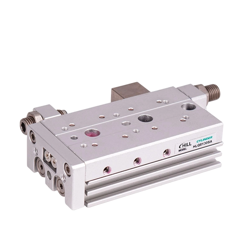
HLQ / HLQL slide tables
Slide-table formats where the moving table forms the tooling interface. Review stroke, mounting faces, permitted load and moment, and the space needed for travel.
Review HLQ / HLQL Series
4V directional valves
Match port count, valve positions and the required normal state to the circuit. Confirm the complete valve code, coil supply, flow requirement, exhaust and mounting arrangement.
Review 4V Series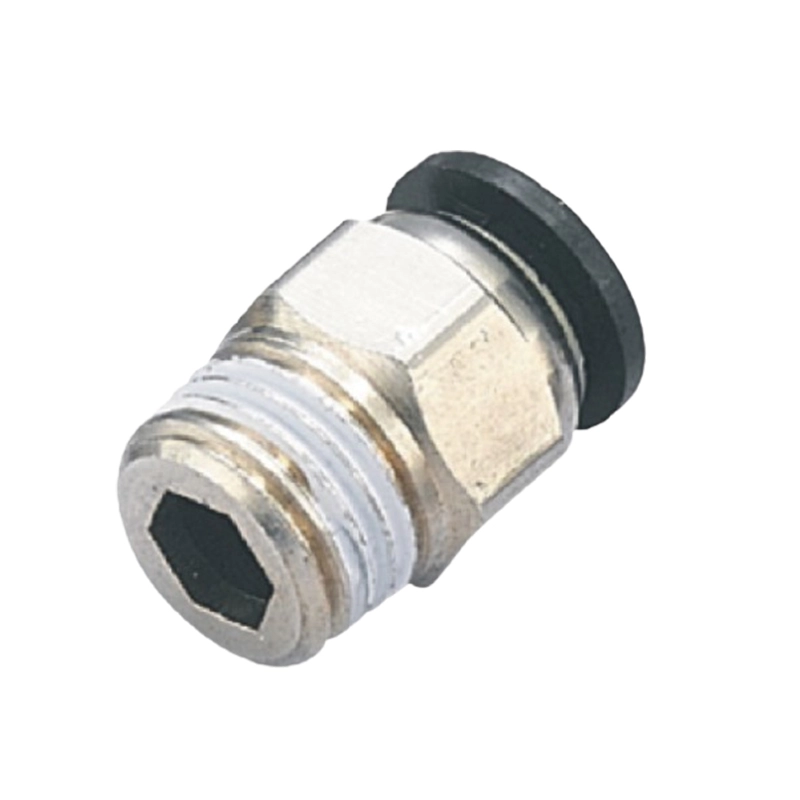
PC push-in connectors
Male straight connections for a defined tube and threaded port. Specify tube outside diameter, thread standard, nominal size and the permitted operating conditions.
Review PC Series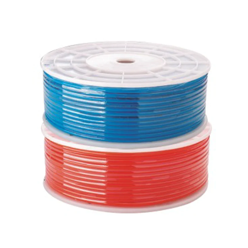
PU pneumatic tubing
Flexible air routing between the selected components. Confirm outside and inside diameter, length, bend route, motion and the pressure–temperature conditions for the actual tube.
Review PU SeriesA clear assembly-station package.
Review the mechanism, controls and air lines as one arrangement.
Mechanism and load
Payload and tooling mass, overhang, orientation, mounting faces, guide format and travel envelope.
Control and sensing
Circuit and intended valve state, coil supply, sensor type, connector and controller input requirements.
Pneumatic installation
Required motion timing, available pressure, valve location, exhaust route and moving-tube layout.
Keep the drawing tied to the variant.
Use the full actuator and valve designations, including guide format, stroke, sensor and mounting options. If a dimension or permissible load is missing for the selected configuration, identify that requirement before approving the installation.
Prepare a requirement briefCreate text locally, then copy or download it. No online submission is made by this tool.
- Guided-cylinder technical referencesReview the construction, selected size, mounting and any source drawings available for the series.
- Slide-table technical referencesCheck the moving-table interfaces and selected-model operating and load information.
- New-machine component checklistCollect the load, circuit, mounting, sensing, air-line and document inputs for a new assembly station.
- Available documentation and remaining requirementsCheck the actual source material before relying on a selected-model drawing, manual or certificate.