
SAI Series Pneumatic Cylinders
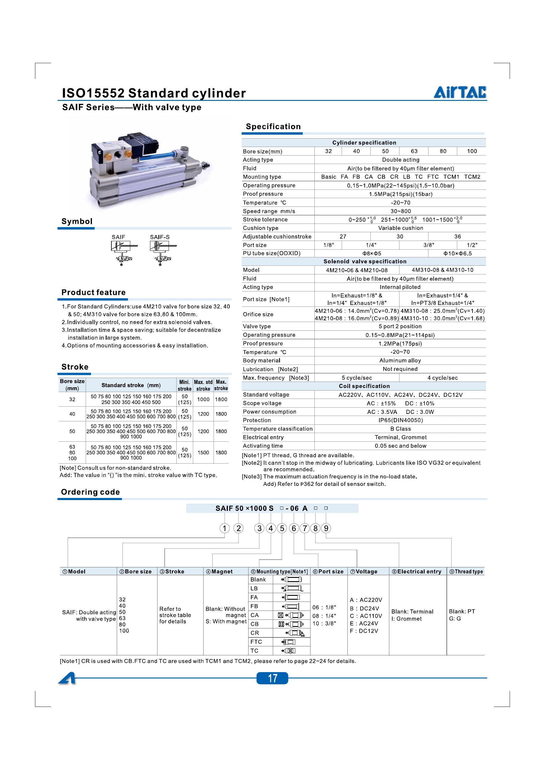
A double-acting profile cylinder platform with sensor grooves on two sides. Compare SAI single rod, SAID double rod and SAIJ adjustable stroke; keep SAIL lock-type and SAIF valve-type configurations within their own documented ranges.
- SAI / SAID / SAIJ bores
- 32–200 mm
- SAIL lock-type bores
- 40–200 mm
- SAIF valve-type bores
- 32–100 mm
Match the model before comparing bore and stroke.
SAI and SAIL values follow the 2022 AirTAC reference; SAIF values come from a separate catalog excerpt and require confirmation for the offered assembly. Match the model and bore first, then check cushioning, stroke, thread and any valve or coil rating.
| Parameter | Catalog reference |
|---|---|
| Acting type | Double acting |
| Working medium | Air filtered through a 40 μm element |
| Cylinder operating pressure | 0.15–1.0 MPa |
| Cylinder proof pressure | 1.5 MPa |
| Standard temperature | −20 to +70 °C |
| End cushioning | Variable air cushion |
| Port thread | Use the configuration-specific ordering reference below |
These are cylinder-side conditions for the documented SAI, SAIL and SAIF configurations. Proof pressure is a test value. SAIF valve conditions are listed separately below.
| Bore (mm) | Port size | Speed (mm/s) | Cushion stroke (mm) |
|---|---|---|---|
| 32 | 1/8″ | 30–800 | 27 |
| 40 | 1/4″ | 30–800 | 27 |
| 50 | 1/4″ | 30–800 | 30 |
| 63 | 3/8″ | 30–800 | 30 |
| 80 | 3/8″ | 30–800 | 36 |
| 100 | 1/2″ | 30–800 | 36 |
| 125 | 1/2″ | 30–500 | 40 |
| 160 | 3/4″ | 30–500 | 50 |
| 200 | 3/4″ | 30–500 | 50 |
The 125–200 mm group has the lower listed speed range. Nominal port size does not identify the thread standard.
Scroll the table horizontally to compare all columns.
| Bore (mm) | Port size | Speed (mm/s) | No-lock end cushion (mm) | Lock end cushion (mm) |
|---|---|---|---|---|
| 40 | 1/4″ | 30–800 | 27 | 20 |
| 50 | 1/4″ | 30–800 | 30 | 20 |
| 63 | 3/8″ | 30–800 | 30 | 21 |
| 80 | 3/8″ | 30–800 | 36 | 22.5 |
| 100 | 1/2″ | 30–800 | 36 | 24 |
| 125 | 1/2″ | 30–500 | 40 | 24 |
| 160 | 3/4″ | 30–500 | 50 | 28 |
| 200 | 3/4″ | 30–500 | 50 | 28 |
Use the lock-end row for the end fitted with the SAIL locking arrangement. These catalog rows do not establish a rated holding force or a safety function.
Scroll the table horizontally to compare all columns.
| Bore (mm) | Cylinder port | Speed (mm/s) | Cushion (mm) | PU tube OD × ID (mm) | Valve family |
|---|---|---|---|---|---|
| 32 | 1/8″ | 30–800 | 27 | 8 × 5 | 4M210 |
| 40 | 1/4″ | 30–800 | 27 | 8 × 5 | 4M210 |
| 50 | 1/4″ | 30–800 | 30 | 8 × 5 | 4M210 |
| 63 | 3/8″ | 30–800 | 30 | 8 × 5 | 4M310 |
| 80 | 3/8″ | 30–800 | 36 | 10 × 6.5 | 4M310 |
| 100 | 1/2″ | 30–800 | 36 | 10 × 6.5 | 4M310 |
The source groups tube size at 32–63 and 80–100 mm; valve family changes between 50 and 63 mm. Do not treat these as the same grouping.
Scroll the table horizontally to compare all columns.
| Bore (mm) | Listed standard strokes (mm) | Max. standard stroke (mm) | Max. stroke (mm) |
|---|---|---|---|
| 32 | 25, 50, 75, 80, 100, 125, 150, 160, 175, 200, 250, 300, 350, 400, 450, 500 | 1000 | 1800 |
| 40 | 25, 50, 75, 80, 100, 125, 150, 160, 175, 200, 250, 300, 350, 400, 450, 500, 600, 700, 800 | 1200 | 1800 |
| 50 | 25, 50, 75, 80, 100, 125, 150, 160, 175, 200, 250, 300, 350, 400, 450, 500, 600, 700, 800, 900, 1000 | 1200 | 1800 |
| 63, 80, 100, 125 | 25, 50, 75, 80, 100, 125, 150, 160, 175, 200, 250, 300, 350, 400, 450, 500, 600, 700, 800, 900, 1000 | 1500 | 1800 |
| 160, 200 | 25, 50, 75, 80, 100, 125, 150, 160, 175, 200, 250, 300, 350, 400, 450, 500, 600, 700, 800, 900, 1000 | 1500 | 2000 |
The listed selections, maximum standard stroke and maximum stroke are separate source columns. Confirm a special stroke before ordering.
Scroll the table horizontally to compare all columns.
| Bore (mm) | Listed standard strokes (mm) | Max. standard stroke (mm) | Max. stroke (mm) |
|---|---|---|---|
| 40 | 25, 50, 75, 80, 100, 125, 150, 160, 175, 200, 250, 300, 350, 400, 450, 500, 600, 700, 800 | 1200 | 1800 |
| 50 | 25, 50, 75, 80, 100, 125, 150, 160, 175, 200, 250, 300, 350, 400, 450, 500, 600, 700, 800, 900, 1000 | 1200 | 1800 |
| 63, 80, 100, 125 | 25, 50, 75, 80, 100, 125, 150, 160, 175, 200, 250, 300, 350, 400, 450, 500, 600, 700, 800, 900, 1000 | 1500 | 1800 |
| 160, 200 | 25, 50, 75, 80, 100, 125, 150, 160, 175, 200, 250, 300, 350, 400, 450, 500, 600, 700, 800, 900, 1000 | 1500 | 2000 |
SAIL starts at 40 mm bore in this reference. Request confirmation for a non-standard stroke and the complete locking configuration.
Scroll the table horizontally to compare all columns.
| Bore (mm) | Listed standard strokes (mm) | Min. stroke (mm) | Min. with TC (mm) | Max. standard (mm) | Max. stroke (mm) |
|---|---|---|---|---|---|
| 32 | 50, 75, 80, 100, 125, 150, 160, 175, 200, 250, 300, 350, 400, 450, 500 | 50 | 125 | 1000 | 1800 |
| 40 | 50, 75, 80, 100, 125, 150, 160, 175, 200, 250, 300, 350, 400, 450, 500, 600, 700, 800 | 50 | 125 | 1200 | 1800 |
| 50 | 50, 75, 80, 100, 125, 150, 160, 175, 200, 250, 300, 350, 400, 450, 500, 600, 700, 800, 900, 1000 | 50 | 125 | 1200 | 1800 |
| 63, 80, 100 | 50, 75, 80, 100, 125, 150, 160, 175, 200, 250, 300, 350, 400, 450, 500, 600, 700, 800, 900, 1000 | 50 | 125 | 1500 | 1800 |
The bracketed 125 mm minimum in the original table applies to TC mounting. SAIF standard stroke listings begin at 50 mm; do not inherit the 25 mm listing from the base SAI table.
Scroll the table horizontally to compare all columns.
| Stroke range (mm) | Positive tolerance (mm) | Negative tolerance (mm) |
|---|---|---|
| 0–250 | +1.0 | 0 |
| 251–1000 | +1.5 | 0 |
| 1001–1500 | +2.0 | 0 |
Apply only a band within the selected model’s allowed stroke range. The source lists no tolerance band above 1500 mm; do not extrapolate one for the maximum-stroke limits.
| Parameter | Catalog reference |
|---|---|
| Documented valves | 4M210-06 / 4M210-08; 4M310-08 / 4M310-10 |
| Actuation | Internal piloted |
| Valve function | 5 port, 2 position |
| Operating pressure | 0.15–0.8 MPa |
| Proof pressure | 1.2 MPa |
| Temperature | −20 to +70 °C |
| Body material | Aluminum alloy |
| Lubrication | Not required |
| 4M210 maximum frequency | 5 cycles/s, no-load reference |
| 4M310 maximum frequency | 4 cycles/s, no-load reference |
The integrated valve has a lower operating/proof-pressure reference than the cylinder. Check both ratings for the complete assembly. If lubrication is introduced, the original note requires it to continue and recommends ISO VG32 or equivalent.
| Valve | Nominal inlet / exhaust | Catalog orifice area (mm²) | Cv |
|---|---|---|---|
| 4M210-06 | 1/8″ / 1/8″ | 14.0 | 0.78 |
| 4M210-08 | 1/4″ / 1/8″ | 16.0 | 0.89 |
| 4M310-08 | 1/4″ / 1/4″ | 25.0 | 1.40 |
| 4M310-10 | 3/8″ / 1/4″ | 30.0 | 1.68 |
These are the valve-side inlet/exhaust references, separate from the cylinder port row. Specify the valve model and thread standard.
Scroll the table horizontally to compare all columns.
| Parameter | Catalog reference |
|---|---|
| Listed voltages | AC220V, AC110V, AC24V, DC24V or DC12V |
| Voltage tolerance | AC: ±15%; DC: ±10% |
| Power consumption | AC: 3.5 VA; DC: 3.0 W |
| Catalog protection label | IP65 (DIN40050) |
| Temperature classification | B class |
| Electrical entry | Terminal or grommet |
| Actuating time | 0.05 s or less |
Confirm the selected coil, connector and electrical assembly. The printed protection label is a source reference, not an independently verified rating for an offered assembly.
Keep each configuration within its own ordering fields.
The base SAI rod arrangements and SAIL lock positions use the 2022 reference shown here. SAIF uses a separate valve/coil code. Select each arrangement with its own dimensional and thread references before completing the model.
Documented configurations
| Code | Arrangement | Documented bore range |
|---|---|---|
| SAI | Single rod, double acting | 32–200 mm |
| SAID | Double rod, double acting | 32–200 mm |
| SAIJ | Adjustable-stroke, double acting | 32–200 mm |
| SAIL | Double acting with front- or rear-cover lock | 40–200 mm |
| SAIF | Double acting with mounted solenoid valve | 32–100 mm |
Use each model’s own dimensional reference. SAI/SAID/SAIJ and SAIL drawings are shown below; request the current external drawing for an offered SAIF assembly.
SAI / SAID / SAIJ order options
| Field | Catalog-listed options |
|---|---|
| Bore | 32, 40, 50, 63, 80, 100, 125, 160 or 200 mm |
| Rod material | Blank: medium carbon steel; A: SUS420J2; B: SUS304 |
| Stroke | Select a stroke in mm from the base SAI table |
| SAIJ adjustment | 10, 20, 30, 40, 50, 75 or 100 mm; no adjustment code for SAI/SAID |
| Magnet | Blank: without magnet; S: with magnet |
| SAI mounting | Basic, FA, FB, CA, CB, CR, LB, TC, FTC, TCM1, TCM2 |
| SAID / SAIJ mounting | Basic, FA, LB, TC, FTC, TCM1, TCM2 |
| Seals | Blank: TPU; H: Viton; N: NBR |
| Thread | G: G thread in the 2022 regional ordering reference; confirm the offered model |
The 2022 reference pairs CR with CB and FTC/TC with TCM1/TCM2. It lists G in the ordering code and refers mounting accessories to printed pp.240–242. Confirm the actual supplied complete code and thread.
SAIL lock-type order options
| Field | Catalog-listed options |
|---|---|
| Bore | 40, 50, 63, 80, 100, 125, 160 or 200 mm |
| Lock position | B: back cover with lock; F: front cover with lock |
| Stroke | Select a stroke in mm from the SAIL table |
| Magnet | Blank: without magnet; S: with magnet |
| Mounting | Basic, FA, FB, CA, CB, CR, LB, TC, FTC, TCM1, TCM2 |
| Thread | G: G thread in the 2022 regional ordering diagram; confirm other requested threads |
The 2022 SAIL specification note mentions PT and G, while its ordering diagram lists only G. Confirm the requested thread and complete code with the supplier. This code has no separate rod-material or seal-material field; confirm lock operating and holding requirements separately.
SAIF valve-type order options
| Field | Catalog-listed options |
|---|---|
| Bore | 32, 40, 50, 63, 80 or 100 mm |
| Stroke | Select a stroke in mm; respect the 50 mm minimum or 125 mm with TC |
| Magnet | Blank: without magnet; S: with magnet |
| Mounting | Basic, FA, FB, CA, CB, CR, LB, TC, FTC, TCM1, TCM2 |
| Valve port code | 06: 1/8″; 08: 1/4″; 10: 3/8″; match the selected 4M valve group |
| Voltage code | A: AC220V; B: DC24V; C: AC110V; E: AC24V; F: DC12V |
| Electrical entry | Blank: terminal; I: grommet |
| Thread | Blank: PT; G: G |
SAIF uses the separate catalog excerpt, printed p.17. Its code lists PT/G and no separate rod-material or seal-material selector. Match the valve family, port, coil and complete offered model, and request its external drawing.
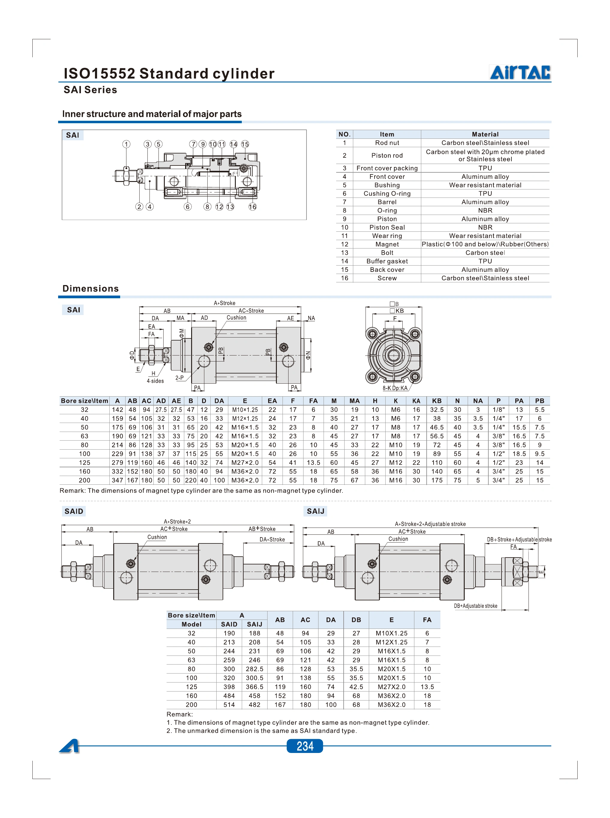
SAI / SAID / SAIJ 2022 specification and ordering reference

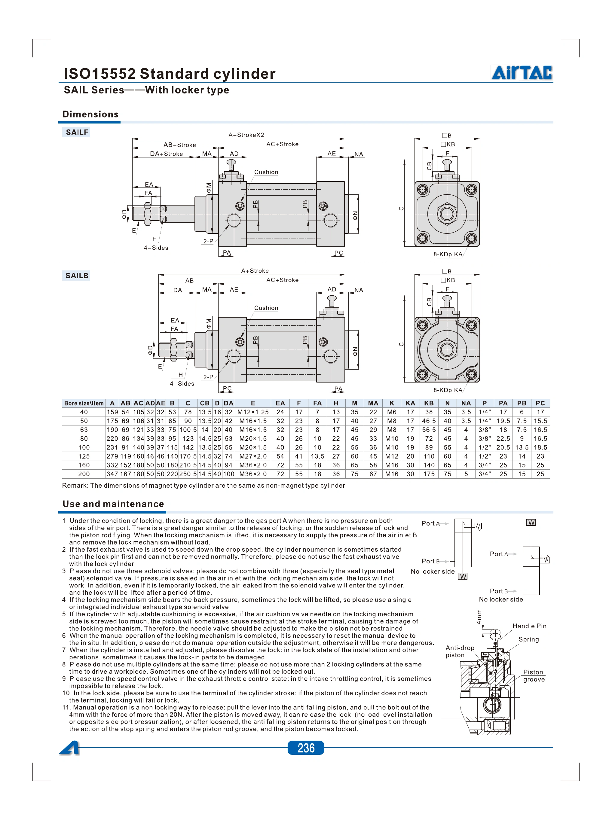
SAIL 2022 specification and ordering reference

SAIF separate cylinder, valve, coil and ordering reference
Use the drawing for the selected cylinder and lock position.
The 2022 reference provides SAI, SAID, SAIJ, SAILF and SAILB drawings. Dimensions are in millimetres unless a thread is identified. Their length formulas and lock envelopes differ. SAIF is documented separately without an external drawing; request its current assembly drawing before fixing the mounting envelope.
| Bore (mm) | Rod ØD | A | Cover □B | Rod thread E | Port P |
|---|---|---|---|---|---|
| 32 | 12 | 142 | 47 | M10 × 1.25 | 1/8″ |
| 40 | 16 | 159 | 53 | M12 × 1.25 | 1/4″ |
| 50 | 20 | 175 | 65 | M16 × 1.5 | 1/4″ |
| 63 | 20 | 190 | 75 | M16 × 1.5 | 3/8″ |
| 80 | 25 | 214 | 95 | M20 × 1.5 | 3/8″ |
| 100 | 25 | 229 | 115 | M20 × 1.5 | 1/2″ |
| 125 | 32 | 279 | 140 | M27 × 2.0 | 1/2″ |
| 160 | 40 | 332 | 180 | M36 × 2.0 | 3/4″ |
| 200 | 40 | 347 | 220 | M36 × 2.0 | 3/4″ |
SAI overall length = A + stroke, as marked in the source. Match the complete mounting, rod projection, ports and thread using the full current drawing; these selected dimensions do not establish replacement fit.
Scroll the table horizontally to compare all columns.
| Bore (mm) | SAID A (mm) | SAIJ A (mm) |
|---|---|---|
| 32 | 190 | 188 |
| 40 | 213 | 208 |
| 50 | 244 | 231 |
| 63 | 259 | 246 |
| 80 | 300 | 282.5 |
| 100 | 320 | 300.5 |
| 125 | 398 | 366.5 |
| 160 | 484 | 458 |
| 200 | 514 | 482 |
SAID overall length = A + 2 × stroke. SAIJ overall length = A + 2 × stroke + adjustable stroke. The original remarks retain magnetic/non-magnetic equivalence and identify unmarked dimensions as those of the base SAI drawing.
Scroll the table horizontally to compare all columns.
| Bore (mm) | A | Cover □B | Height C | Rod thread E | Port P |
|---|---|---|---|---|---|
| 40 | 159 | 53 | 78 | M12 × 1.25 | 1/4″ |
| 50 | 175 | 65 | 90 | M16 × 1.5 | 1/4″ |
| 63 | 190 | 75 | 100.5 | M16 × 1.5 | 3/8″ |
| 80 | 220 | 95 | 123 | M20 × 1.5 | 3/8″ |
| 100 | 231 | 115 | 142 | M20 × 1.5 | 1/2″ |
| 125 | 279 | 140 | 170.5 | M27 × 2.0 | 1/2″ |
| 160 | 332 | 180 | 210.5 | M36 × 2.0 | 3/4″ |
| 200 | 347 | 220 | 250.5 | M36 × 2.0 | 3/4″ |
Use the matching lock-position drawing. The source marks SAILF overall length as A + 2 × stroke and SAILB as A + stroke. SAIL A differs from base SAI at 80 and 100 mm bore. Confirm the selected complete model and lock envelope in the current supplier drawing.
Scroll the table horizontally to compare all columns.
SAI / SAID / SAIJ structure and dimensions — 2022
SAILF / SAILB dimensions and lock maintenance — 2022
SAI platform, thrust and installation reference — 2022

SAI/SAIL technical reference: AirTAC official 2022 catalog, printed pp.232–236. SAIF reference: separate AirTAC catalog excerpt, printed p.17; its external assembly drawing remains required. Confirm the actual supplied complete model, thread and current drawing before ordering; catalog data and the series photograph do not establish manufacture, independent certification or cross-brand fit.
Check load, sensing and the complete installation drawing.
Available pressure, load direction, stroke and travel time determine the selection. A mounting illustration or a matching bore alone does not establish the dimensions of the offered configuration.
- Load and motion
- Provide load, orientation, stroke, travel time and pressure at the cylinder. Check return-side force as well as push-side force and allow capacity for friction and pressure losses.
- Mounting and guidance
- Specify the mounting code, rod joint and available envelope. Keep lateral load off the piston rod and provide suitable guidance where the mechanism imposes side load.
- Lock or valve requirements
- For SAIL state the lock position, load and required sequence; review the original lock-use and maintenance instructions and confirm the holding conditions and current drawing. For SAIF match the valve pressure, flow, port and coil and obtain the assembly envelope.
- Air and sensing
- Clean the pipeline, use the specified filtration and commission without load while adjusting cushioning. The overview names CMSE/DMSE sensors; confirm the selected switch and electrical interface separately.
| Bore (mm) | Push side (N) | Pull side (N) |
|---|---|---|
| 32 | 402.0 | 345.0 |
| 40 | 628.0 | 527.5 |
| 50 | 981.5 | 824.5 |
| 63 | 1558.5 | 1401.5 |
| 80 | 2513.0 | 2268.0 |
| 100 | 3926.5 | 3681.0 |
| 125 | 6136.0 | 5734.0 |
| 160 | 10053.0 | 9424.5 |
| 200 | 15708.0 | 15078.5 |
Values are transcribed as printed in the base SAI catalog at one selected pressure. They do not establish SAIL holding capacity, SAIF assembly performance or actual usable force after application losses.
Scroll the table horizontally to compare all columns.
Specify one complete cylinder configuration.
Include model, bore, stroke, adjustment if needed, pressure, load, mounting, thread, magnet/sensor requirements and quantity. Add the SAIL lock position or SAIF valve/coil fields where applicable. Request the current external drawing and include the full old code and measured mounting dimensions for a replacement.
The brief tool creates text on your device to copy or download. It does not send an online enquiry.
What needs confirmation for a SAIL or SAIF option?
For SAIL confirm the front- or rear-lock position, required holding conditions and matching lock drawing. For SAIF confirm the valve, coil, working pressure and complete external assembly drawing.
What should I check when selecting a replacement cylinder?
Match the complete old code, bore, stroke, mounting-hole pattern, rod-end thread and projection, port positions and available envelope against the current drawing for the offered model.
Does SAIF have the same pressure rating as its cylinder alone?
The cylinder table lists 0.15–1.0 MPa operating pressure and 1.5 MPa proof pressure; the mounted valve table lists 0.15–0.8 MPa and 1.2 MPa. Confirm both sides for the complete assembly.
Which temperature range should I use for selection?
The 2022 SAI/SAIL reference and the separate SAIF cylinder table list −20 to +70 °C. State the actual ambient temperature, medium and duty and confirm the complete offered seal and electrical configuration.