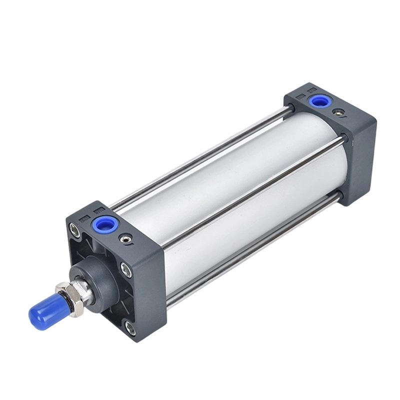
SC Series Tie-Rod Pneumatic Cylinders
Tie rods join the barrel and end covers on this double-acting cylinder platform. Compare SC single rod, SCD double rod and SCJ adjustable stroke in 32–250 mm bores; the documented SCT multi-position range covers 32–100 mm.
- SC / SCD / SCJ bores
- 32–250 mm
- SCT multi-position bores
- 32–100 mm
- End cushioning
- Adjustable air cushioning
Separate the bore ranges and the multi-position strokes.
These catalog references separate small- and large-bore SC cylinders, which have different speed and seal values. SCT uses two stroke fields and its own stroke limits. Confirm the offered complete model against the matching reference.
| Parameter | Catalog reference |
|---|---|
| Acting type | Double acting |
| Working medium | Air filtered through a 40 μm element |
| Operating pressure | 0.15–1.0 MPa |
| Proof pressure | 1.5 MPa |
| Standard temperature | −20 to +70 °C |
| End cushioning | Variable air cushion |
| Port thread options | PT or G; specify the thread type |
These conditions are listed for the documented SC/SCD/SCJ and SCT ranges. Proof pressure is a test value. The separate high-temperature seal reference is not the standard temperature rating.
| Bore (mm) | Port size | Speed (mm/s) | Cushion stroke (mm) |
|---|---|---|---|
| 32 | 1/8″ | 30–800 | 21 |
| 40 | 1/4″ | 30–800 | 21 |
| 50 | 1/4″ | 30–800 | 21 |
| 63 | 3/8″ | 30–800 | 21 |
| 80 | 3/8″ | 30–800 | 28 |
| 100 | 1/2″ | 30–800 | 29 |
| 125 | 1/2″ | 30–500 | 28 |
| 160 | 3/4″ | 30–500 | 29 |
| 200 | 3/4″ | 30–500 | 33 |
| 250 | 1″ | 30–500 | 40 |
The 125–250 mm group uses the large-bore reference. Specify the thread standard as well as nominal port size.
Scroll the table horizontally to compare all columns.
| Bore (mm) | Listed standard strokes (mm) | Max. standard stroke (mm) | Max. stroke (mm) |
|---|---|---|---|
| 32 | 25, 50, 75, 80, 100, 125, 150, 160, 175, 200, 250, 300, 350, 400, 450, 500 | 1000 | 2000 |
| 40, 50 | 25, 50, 75, 80, 100, 125, 150, 160, 175, 200, 250, 300, 350, 400, 450, 500, 600, 700, 800, 900, 1000 | 1200 | 2000 |
| 63, 80, 100 | 25, 50, 75, 80, 100, 125, 150, 160, 175, 200, 250, 300, 350, 400, 450, 500, 600, 700, 800, 900, 1000 | 1500 | 2000 |
| 125, 160, 200, 250 | 25, 50, 75, 80, 100, 125, 150, 160, 175, 200, 250, 300, 350, 400, 450, 500, 600, 700, 800, 900, 1000 | 1500 | 2000 |
Listed stroke selections, maximum standard stroke and maximum stroke are separate catalog columns. The 32–100 mm note treats a stroke of 1600 mm or more within the maximum range as non-standard. Confirm special strokes and their tolerances.
Scroll the table horizontally to compare all columns.
| Bore (mm) | Port size | Speed (mm/s) | Cushion stroke (mm) |
|---|---|---|---|
| 32 | 1/8″ | 30–800 | 21 |
| 40 | 1/4″ | 30–800 | 21 |
| 50 | 1/4″ | 30–800 | 21 |
| 63 | 3/8″ | 30–800 | 21 |
| 80 | 3/8″ | 30–800 | 28 |
| 100 | 1/2″ | 30–800 | 29 |
SCT is documented as a multi-position double-acting cylinder. Its ordering code specifies stroke 1 and stroke 2 separately.
Scroll the table horizontally to compare all columns.
| Bore (mm) | Listed standard strokes (mm) | Max. standard stroke (mm) | Max. stroke (mm) |
|---|---|---|---|
| 32, 40, 50, 63, 80, 100 | 25, 50, 75, 80, 100, 125, 150, 160, 175, 200, 250, 300, 350, 400, 450, 500 | 500 | 800 |
The original SCT note treats a stroke of 800 mm or more within the maximum range as non-standard. Confirm both stroke fields, positions and the complete installation envelope; no SCT dimension drawing is included in this reference.
Scroll the table horizontally to compare all columns.
| Stroke range (mm) | Positive tolerance (mm) | Negative tolerance (mm) |
|---|---|---|
| 0–250 | +1.0 | 0 |
| 251–1000 | +1.5 | 0 |
| 1001–1500 | +2.0 | 0 |
Use only the band applicable to the selected model and its allowed stroke range. The source provides no tolerance band above 1500 mm, although SC maximum stroke is listed as 2000 mm.
Keep the rod layout, seal code and stroke fields together.
The single-rod, double-rod, adjustable-stroke and multi-position arrangements do not share one installation envelope. Select the arrangement first, then use its bore range and ordering fields.
Documented arrangements
| Code | Arrangement | Selection boundary |
|---|---|---|
| SC | Single rod, double acting | 32–250 mm bores; use the matching small- or large-bore drawing |
| SCD | Double rod, double acting | 32–250 mm bores; rod projects from both ends |
| SCJ | Adjustable-stroke, double acting | 32–250 mm bores; specify the adjustment amount |
| SCT | Multi-position, double acting | 32–100 mm bores; two stroke fields, separate stroke limits and a required final dimension drawing |
Ordering fields and mounting
| Field | Catalog-listed options |
|---|---|
| SC / SCD / SCJ bore | 32, 40, 50, 63, 80, 100, 125, 160, 200 or 250 mm |
| SC / SCD / SCJ stroke | Select a stroke in mm from the matching table |
| SCJ adjustment | 10, 20, 30, 40, 50, 75 or 100 mm; no adjustment code for SC/SCD |
| Magnet | Blank: without magnet; S: with magnet |
| SC mounting | Basic, FA, FB, CA, CB, LB, TC, TCM1 |
| SCD / SCJ mounting | Basic, FA, LB, TC, TCM1 |
| SCT selection | 32–100 mm bore; stroke 1 and stroke 2; Basic, FA, FB, CA, CB, LB, TC, TCM1 mounting listed in the specification |
| Thread | Blank: PT; G: G |
TC is used with TCM1. The 32–100 mm SC/SCD/SCJ ordering note says this assembly must be ordered with the cylinder. Mounting accessory dimensions are referenced to other catalog pages and are not included here.
Seal codes by documented range
| Range | Catalog-listed seal codes |
|---|---|
| SC / SCD / SCJ, 32–100 mm | Blank: TPU; H: Viton; N: NBR |
| SC / SCD / SCJ, 125–250 mm | Blank: NBR; H: Viton |
| SCT, 32–100 mm | Blank: TPU; H: Viton; N: NBR |
Do not carry the small-bore blank seal code into the large-bore range. State the required temperature and medium and confirm the offered seal specification.
SC 32–100 mm specification and ordering code

SC 125–250 mm specification and ordering code

SCT multi-position specification and ordering code

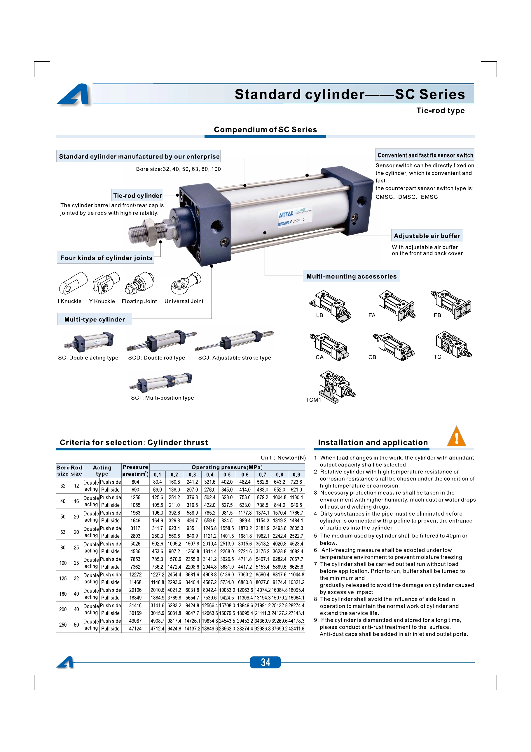
SC platform, thrust and installation reference
Use the drawing for the chosen bore group and rod layout.
Dimensions are in millimetres unless a thread is identified. SC, SCD and SCJ each have a different length formula. The 125–250 mm group has its own dimension and material page. A dimension drawing for SCT is not included; request it before fixing its mounting envelope.
| Bore | Rod ØD | A | Cover □B | Rod thread E | Port P |
|---|---|---|---|---|---|
| 32 | 12 | 140 | 45 | M10 × 1.25 | 1/8″ |
| 40 | 16 | 142 | 50 | M12 × 1.25 | 1/4″ |
| 50 | 20 | 150 | 62 | M16 × 1.5 | 1/4″ |
| 63 | 20 | 153 | 75 | M16 × 1.5 | 3/8″ |
| 80 | 25 | 182 | 94 | M20 × 1.5 | 3/8″ |
| 100 | 25 | 188 | 112 | M20 × 1.5 | 1/2″ |
| 125 | 32 | 203 | 136 | M27 × 2.0 | 1/2″ |
| 160 | 40 | 239 | 174 | M36 × 2.0 | 3/4″ |
| 200 | 40 | 244 | 214 | M36 × 2.0 | 3/4″ |
| 250 | 50 | 294 | 267 | M42 × 2.0 | 1″ |
SC overall length = A + stroke, as marked in the original drawing. Check the full drawing for mounting holes, rod projection and port positions; A and B alone do not establish replacement fit.
Scroll the table horizontally to compare all columns.
| Bore (mm) | SCD A (mm) | SCJ A (mm) |
|---|---|---|
| 32 | 187 | 182 |
| 40 | 191 | 185 |
| 50 | 207 | 194 |
| 63 | 210 | 197 |
| 80 | 257 | 238.5 |
| 100 | 263 | 244.5 |
| 125 | 291 | 265.5 |
| 160 | 352 | 332 |
| 200 | 362 | 342 |
| 250 | 435 | 409 |
SCD overall length = A + 2 × stroke. SCJ overall length = A + 2 × stroke + adjustable stroke. The original remarks say magnetic and non-magnetic dimensions are alike and unmarked variant dimensions follow SC.
Scroll the table horizontally to compare all columns.
SC / SCD / SCJ 32–100 mm dimensions and structure

SC / SCD / SCJ 125–250 mm dimensions and structure

Technical reference: AirTAC SC catalog, printed pp.34–39. Confirm the offered complete model and current drawing before ordering. These source references do not establish JEMWON manufacture, certification or cross-brand interchangeability.
Size for the load and verify the complete travel envelope.
Use pressure at the cylinder, travel time and load direction to choose the bore. Compare both push-side and return-side force, then check alignment and end cushioning.
- Load and motion
- Provide the load, orientation, stroke, travel time and pressure at the cylinder. Leave capacity for friction, pressure losses and changing load.
- Mounting and alignment
- Choose the mounting and joint arrangement from the selected model. Keep lateral load off the piston rod and provide suitable guidance where the mechanism imposes side load.
- Air and commissioning
- Clean the pipeline before connection, use the specified filtration and commission without load while adjusting cushioning. Address moisture, contamination and freezing conditions in the installation.
- Position sensing and SCT
- The source names CMSG, DMSG and EMSG sensor types but does not include their electrical specifications. Specify magnet and switch requirements separately. For SCT, supply both required travel positions and obtain the complete dimension drawing.
| Bore (mm) | Push side (N) | Pull side (N) |
|---|---|---|
| 32 | 402.0 | 345.0 |
| 40 | 628.0 | 527.5 |
| 50 | 981.5 | 824.5 |
| 63 | 1558.5 | 1401.5 |
| 80 | 2513.0 | 2268.0 |
| 100 | 3926.5 | 3681.0 |
| 125 | 6136.0 | 5734.0 |
| 160 | 10053.0 | 9424.5 |
| 200 | 15708.0 | 15079.5 |
| 250 | 24543.5 | 23562.0 |
The original SC table lists these values at 0.5 MPa. Actual usable force depends on friction, pressure losses and the application; this table does not establish SCT multi-position performance.
Scroll the table horizontally to compare all columns.
Specify the complete SC or SCT arrangement.
Include model, bore, stroke, adjustment where required, pressure, load, mounting, bore-specific seal code, magnet/sensor requirements, thread and quantity. For SCT include stroke 1, stroke 2 and the required positions. For a replacement include the full old code and measured mounting dimensions.
The brief tool creates text on your device to copy or download. It does not send an online enquiry.
Is the blank seal code the same for every SC bore?
No. The documented 32–100 mm SC range uses blank for TPU; the 125–250 mm SC range uses blank for NBR. Match the code to the bore-specific ordering table.
Can SCT use the SC 2000 mm maximum stroke?
Use the separate SCT table, which lists 500 mm maximum standard stroke and 800 mm maximum stroke. Confirm its two stroke fields and final dimension drawing rather than applying SC limits.
Is 150 °C the standard working temperature?
The standard specification is −20 to +70 °C. The source discusses a high-temperature seal arrangement separately; state the required temperature and confirm the complete offered specification.
Does the S magnet option include a position switch?
S identifies the magnet option in the cylinder code. Specify the switch separately and confirm its mounting and electrical interface.