Mini pneumatic
cylinders.
Micro, single-acting and round-body formats for smaller machine spaces. Compare seven series groups by return action, mounting, ports and cushioning.

Seven series groups.
Different small-space formats.
Start with return action, body format and the available mounting space. Review the selected series for its own operating, stroke and port data.
PB Series
Ultra-small mechanisms with acting and rod variants. Check the bore-specific tube connection or M5 interface.

MPE Series
Single-acting micro motion in a short body. Compare the embedded MPE layout with the MPEF end inlet.

MI / MIC Series
A narrow-body platform with several acting and cushioning options. Match the complete MI or MIC variant to the motion.

MF Series
A mini-cylinder platform with pipe-port options. Compare rear mounting, rod arrangement and installation length.

MG / MGC Series
Variable cushioning with bore-specific ports. Confirm the available bore and rod variant together.

MA Series
Rear-cover and rod configurations for different mounting layouts. The complete code determines bore and cushioning options.

MBL / MBLC Series
A long-body miniature format. Check stroke clearance, mounting alignment and any external guidance for the load.
Choose the format.
Confirm the return action.
Micro bodies, spring-return models and longer round-body cylinders solve different installation needs. Compare the complete variant before choosing bore and stroke.
| Series group | Format and action | What to confirm |
|---|---|---|
| PB Series | Ultra-small body; acting and rod variants | Bore-specific tube or M5 connection, return action and the available rod format. |
| MPE Series | Short, single-acting micro body | Embedded MPE or end-inlet MPEF layout, return direction and short-stroke selection. |
| MI / MIC Series | Narrow round body; multiple acting types | Full cushion and rod suffix. MIC variants use variable cushioning; other listed variants use bumpers. |
| MF Series | Round body with pipe-port options | Rear mounting and rod clearance. The selected bore controls the port and stroke row. |
| MG / MGC Series | Variable-cushion mini platform | Available bore and rod variant. MG uses M5 at a 20 mm bore; confirm the port for the selected platform. |
| MA Series | Alternative rear-cover and rod layouts | Complete code and mounting envelope. MAC, MACD, MACJ and MAR use variable cushioning. |
| MBL / MBLC Series | Long-body miniature format | MBL or cushioned MBLC variant, stroke clearance, alignment and external guidance. |
Single-acting variants have their own stroke and pressure limits. A listed long stroke does not establish allowable side load or bending capacity.
Series-specific
technical data.
Open a series for its operating conditions, configuration and stroke selection. Apply each row to its listed bore and complete variant; confirm the mounting drawing before ordering.
PB SeriesOperating data · Acting and rod variants
Scroll the table sideways to compare all variant, bore, port and stroke columns. Keyboard: focus the table area, then use the left and right arrow keys.
| Variant | Acting | Bore (mm) | Port size | Listed standard strokes (mm) | Max. standard stroke (mm) |
|---|---|---|---|---|---|
| PB | Double acting | 4 | Tube | 5 10 15 20 | 20 |
| PB | Double acting | 6 | M5×0.8 | 10 15 20 25 30 40 50 60 | 60 |
| PB | Double acting | 10 | M5×0.8 | 10 15 20 25 30 40 50 60 75 80 100 125 150 160 175 200 | 200 |
| PB | Double acting | 12 | M5×0.8 | 10 15 20 25 30 40 50 60 75 80 100 125 150 160 175 200 | 200 |
| PB | Double acting | 16 | M5×0.8 | 10 15 20 25 30 40 50 60 75 80 100 125 150 160 175 200 250 300 | 300 |
Stroke availability depends on the complete model, acting type and options. Confirm the configuration and mounting drawing before ordering.
Scroll the table sideways to compare all variant, bore, port and stroke columns. Keyboard: focus the table area, then use the left and right arrow keys.
| Variant | Acting | Bore (mm) | Port size | Listed standard strokes (mm) | Max. standard stroke (mm) |
|---|---|---|---|---|---|
| PBD / PBJ | Double acting | 10 | M5×0.8 | 10 15 20 25 30 40 50 60 75 80 100 | 100 |
| PBD / PBJ | Double acting | 12 | M5×0.8 | 10 15 20 25 30 40 50 60 75 80 100 125 150 160 175 200 | 200 |
| PBD / PBJ | Double acting | 16 | M5×0.8 | 10 15 20 25 30 40 50 60 75 80 100 125 150 160 175 200 | 200 |
Stroke availability depends on the complete model, acting type and options. Confirm the configuration and mounting drawing before ordering.
Scroll the table sideways to compare all variant, bore, port and stroke columns. Keyboard: focus the table area, then use the left and right arrow keys.
| Variant | Acting | Bore (mm) | Port size | Listed standard strokes (mm) | Notes |
|---|---|---|---|---|---|
| PSB / PTB | Single acting | 6 | M5×0.8 | 5 10 15 20 25 30 40 50 60 | Common |
| PSB / PTB | Single acting | 10 / 12 / 16 | M5×0.8 | 5 10 15 20 25 30 40 50 60 | Common |
Stroke availability depends on the complete model, acting type and options. Confirm the configuration and mounting drawing before ordering.
MPE SeriesOperating data · Single-acting stroke selection
Scroll the table sideways to compare all variant, bore, port and stroke columns. Keyboard: focus the table area, then use the left and right arrow keys.
| Variant | Acting | Bore (mm) | Port size | Listed standard strokes (mm) | Max. standard stroke (mm) |
|---|---|---|---|---|---|
| MPE / MPEF | Single acting | 6 / 8 / 10 / 12 / 16 | M5×0.8 | 5 10 15 | 15 |
Stroke availability depends on the complete model, acting type and options. Confirm the configuration and mounting drawing before ordering.
MI / MIC SeriesOperating data · Acting, cushion and rod variants
Scroll the table sideways to compare all variant, bore, port and stroke columns. Keyboard: focus the table area, then use the left and right arrow keys.
| Variant | Acting | Bore (mm) | Port size | Listed standard strokes (mm) | Max. standard stroke (mm) |
|---|---|---|---|---|---|
| MI / MIC | Double acting | 8 | M5×0.8 | 10 15 20 25 30 40 50 60 75 80 100 125 150 | 150 |
| MI / MIC | Double acting | 10 | M5×0.8 | 10 15 20 25 30 40 50 60 75 80 100 125 150 160 175 200 | 200 |
| MI / MIC | Double acting | 12 | M5×0.8 | 10 15 20 25 30 40 50 60 75 80 100 125 150 160 175 200 250 | 250 |
| MI / MIC | Double acting | 16 | M5×0.8 | 10 15 20 25 30 40 50 60 75 80 100 125 150 160 175 200 250 300 | See long-stroke options |
| MI / MIC | Double acting | 20 / 25 / 32 | 1/8 | 10 15 20 25 30 40 50 60 75 80 100 125 150 160 175 200 250 300 | See long-stroke 350–500 |
| MI / MIC | Double acting | 40 | 1/4 | 10 15 20 25 30 40 50 60 75 80 100 125 150 160 175 200 250 300 | See long-stroke 350–500 |
| Long stroke | Double acting | 20 / 25 / 32 / 40 | By bore | 350 400 450 500 | 500 |
Stroke availability depends on the complete model, acting type and options. Confirm the configuration and mounting drawing before ordering.
Scroll the table sideways to compare all variant, bore, port and stroke columns. Keyboard: focus the table area, then use the left and right arrow keys.
| Variant | Acting | Bore (mm) | Port size | Listed standard strokes (mm) | Max. standard stroke (mm) |
|---|---|---|---|---|---|
| MID (double rod) | Double acting | 8 / 10 | M5×0.8 | 10 15 20 25 30 40 50 60 75 80 100 | 100 |
| MID (double rod) | Double acting | 12 | M5×0.8 | 10 15 20 25 30 40 50 60 75 80 100 125 150 160 175 200 | 200 |
| MIJ (adjustable) | Double acting | 16 / 20 / 25 | 16:M5 · 20–25:1/8 | 10 15 20 25 30 40 50 60 75 80 100 125 150 160 175 200 250 300 | 300 |
| MICD / MICJ | Double acting | 32 / 40 | 32:1/8 · 40:1/4 | 10 15 20 25 30 40 50 60 75 80 100 125 150 160 175 200 250 300 350 400 450 500 | 500 |
Stroke availability depends on the complete model, acting type and options. Confirm the configuration and mounting drawing before ordering.
Scroll the table sideways to compare all variant, bore, port and stroke columns. Keyboard: focus the table area, then use the left and right arrow keys.
| Variant | Acting | Bore (mm) | Port size | Listed standard strokes (mm) | Notes |
|---|---|---|---|---|---|
| MSI | Single acting | 8 / 10 / 12 | M5×0.8 | 10 15 20 25 30 40 50 | Common |
| MSI | Single acting | 16 | M5×0.8 | 10 15 20 25 30 40 50 60 75 80 100 | Common |
| MSI / MTI | Single acting | 20 / 25 / 32 / 40 | 20–32:1/8 · 40:1/4 | 10 15 20 25 30 40 50 60 75 80 100 125 150 | Common |
Stroke availability depends on the complete model, acting type and options. Confirm the configuration and mounting drawing before ordering.
MF SeriesOperating data · Acting, cushion and rod variants
Scroll the table sideways to compare all variant, bore, port and stroke columns. Keyboard: focus the table area, then use the left and right arrow keys.
| Variant | Acting | Bore (mm) | Port size | Listed standard strokes (mm) | Max. standard stroke (mm) |
|---|---|---|---|---|---|
| MF / MFC | Double acting | 20 / 25 / 32 | 1/8 | 10 15 20 25 30 40 50 60 75 80 100 125 150 160 175 200 250 300 350 400 450 500 | 500 |
| MF / MFC | Double acting | 40 | 1/4 | 10 15 20 25 30 40 50 60 75 80 100 125 150 160 175 200 250 300 350 400 450 500 | 500 |
Stroke availability depends on the complete model, acting type and options. Confirm the configuration and mounting drawing before ordering.
Scroll the table sideways to compare all variant, bore, port and stroke columns. Keyboard: focus the table area, then use the left and right arrow keys.
| Variant | Acting | Bore (mm) | Port size | Listed standard strokes (mm) | Max. standard stroke (mm) |
|---|---|---|---|---|---|
| MFD / MFCD / MFJ / MFCJ | Double acting | 20 / 25 | 1/8 | 10 15 20 25 30 40 50 60 75 80 100 125 150 160 175 200 250 300 | 300 |
| MFD / MFCD / MFJ / MFCJ | Double acting | 32 | 1/8 | 10 15 20 25 30 40 50 60 75 80 100 125 150 160 175 200 250 300 350 400 450 500 | 500 |
| MFD / MFCD / MFJ / MFCJ | Double acting | 40 | 1/4 | 10 15 20 25 30 40 50 60 75 80 100 125 150 160 175 200 250 300 350 400 450 500 | 500 |
Stroke availability depends on the complete model, acting type and options. Confirm the configuration and mounting drawing before ordering.
Scroll the table sideways to compare all variant, bore, port and stroke columns. Keyboard: focus the table area, then use the left and right arrow keys.
| Variant | Acting | Bore (mm) | Port size | Listed standard strokes (mm) | Notes |
|---|---|---|---|---|---|
| MSF / MTF | Single acting | 20 / 25 / 32 / 40 | 20–32:1/8 · 40:1/4 | 10 15 20 25 30 40 50 60 75 80 100 125 150 | Common |
Stroke availability depends on the complete model, acting type and options. Confirm the configuration and mounting drawing before ordering.
MG / MGC SeriesOperating data · Bore-specific ports and strokes
Scroll the table sideways to compare all variant, bore, port and stroke columns. Keyboard: focus the table area, then use the left and right arrow keys.
| Variant | Acting | Bore (mm) | Port size | Listed standard strokes (mm) | Max. standard stroke (mm) |
|---|---|---|---|---|---|
| MG / MGC | Double acting | 20 | M5×0.8 | 10 15 20 25 30 40 50 60 75 80 100 125 150 175 200 (201–500 optional) | 500 |
| MG / MGC | Double acting | 25 / 32 / 40 | 1/8 | 10 15 20 25 30 40 50 60 75 80 100 125 150 160 175 200 250 300 (301–500 optional) | 500 |
| MGC | Double acting | 50 / 63 | 1/4 | 10 15 20 25 30 40 50 60 75 80 100 125 150 160 175 200 250 300 (301–500 optional) | 500 |
Stroke availability depends on the complete model, acting type and options. Confirm the configuration and mounting drawing before ordering.
Scroll the table sideways to compare all variant, bore, port and stroke columns. Keyboard: focus the table area, then use the left and right arrow keys.
| Variant | Acting | Bore (mm) | Port size | Listed standard strokes (mm) | Max. standard stroke (mm) |
|---|---|---|---|---|---|
| MGD / MGCD | Double acting | 20 / 25 | 20:M5 · 25:1/8 | 10 15 20 25 30 40 50 60 75 80 100 125 150 160 175 200 250 300 | 300 |
Stroke availability depends on the complete model, acting type and options. Confirm the configuration and mounting drawing before ordering.
Scroll the table sideways to compare all variant, bore, port and stroke columns. Keyboard: focus the table area, then use the left and right arrow keys.
| Variant | Acting | Bore (mm) | Port size | Listed standard strokes (mm) | Notes |
|---|---|---|---|---|---|
| MSG / MTG | Single acting | 20 / 25 / 32 / 40 | 20:M5 · 25–40:1/8 | 10 15 20 25 30 40 50 60 75 80 100 125 150 | Common |
Stroke availability depends on the complete model, acting type and options. Confirm the configuration and mounting drawing before ordering.
MA SeriesOperating data · Rear-cover and rod variants
Scroll the table sideways to compare all variant, bore, port and stroke columns. Keyboard: focus the table area, then use the left and right arrow keys.
| Variant | Acting | Bore (mm) | Port size | Listed standard strokes (mm) | Max. standard stroke (mm) |
|---|---|---|---|---|---|
| MA / MAC / MAR | Double acting | 20 / 25 / 32 / 40 | 1/8 | 10 15 20 25 30 40 50 60 75 80 100 125 150 160 175 200 250 300 350 400 450 500 | 500 |
| MAC / MAR | Double acting | 50 / 63 | 1/4 | 10 15 20 25 30 40 50 60 75 80 100 125 150 160 175 200 250 300 350 400 450 500 | 500 |
Stroke availability depends on the complete model, acting type and options. Confirm the configuration and mounting drawing before ordering.
Scroll the table sideways to compare all variant, bore, port and stroke columns. Keyboard: focus the table area, then use the left and right arrow keys.
| Variant | Acting | Bore (mm) | Port size | Listed standard strokes (mm) | Max. standard stroke (mm) |
|---|---|---|---|---|---|
| MAD / MAJ / MACD / MACJ | Double acting | 16 / 20 / 25 | 16:M5 · 20–25:1/8 | 10 15 20 25 30 40 50 60 75 80 100 125 150 160 175 200 250 300 | 300 |
Stroke availability depends on the complete model, acting type and options. Confirm the configuration and mounting drawing before ordering.
Scroll the table sideways to compare all variant, bore, port and stroke columns. Keyboard: focus the table area, then use the left and right arrow keys.
| Variant | Acting | Bore (mm) | Port size | Listed standard strokes (mm) | Notes |
|---|---|---|---|---|---|
| MSA / MTA | Single acting | 16 / 20 / 25 / 32 / 40 | 16:M5 · 20–40:1/8 | 10 15 20 25 30 40 50 60 75 80 100 125 150 | Common |
Stroke availability depends on the complete model, acting type and options. Confirm the configuration and mounting drawing before ordering.
MBL / MBLC SeriesOperating data · Rod and single-acting variants
Scroll the table sideways to compare all variant, bore, port and stroke columns. Keyboard: focus the table area, then use the left and right arrow keys.
| Variant | Acting | Bore (mm) | Port size | Listed standard strokes (mm) | Max. standard stroke (mm) |
|---|---|---|---|---|---|
| MBL / MBLC | Double acting | 20 / 25 / 32 / 40 | 1/8 | 10 15 20 25 30 40 50 60 75 80 100 125 150 160 175 200 250 300 350 400 450 500 | 500 |
| MBL / MBLC | Double acting | 50 / 63 | 1/4 | 10 15 20 25 30 40 50 60 75 80 100 125 150 160 175 200 250 300 350 400 450 500 | 500 |
Stroke availability depends on the complete model, acting type and options. Confirm the configuration and mounting drawing before ordering.
Scroll the table sideways to compare all variant, bore, port and stroke columns. Keyboard: focus the table area, then use the left and right arrow keys.
| Variant | Acting | Bore (mm) | Port size | Listed standard strokes (mm) | Max. standard stroke (mm) |
|---|---|---|---|---|---|
| MBLD / MBLCD | Double acting | 20 / 25 | 1/8 | 10 15 20 25 30 40 50 60 75 80 100 125 150 160 175 200 250 300 | 300 |
| MBLD / MBLCD | Double acting | 32 / 40 | 1/8 | 10 15 20 25 30 40 50 60 75 80 100 125 150 160 175 200 250 300 350 400 450 500 | 500 |
Stroke availability depends on the complete model, acting type and options. Confirm the configuration and mounting drawing before ordering.
Scroll the table sideways to compare all variant, bore, port and stroke columns. Keyboard: focus the table area, then use the left and right arrow keys.
| Variant | Acting | Bore (mm) | Port size | Listed standard strokes (mm) | Max. standard stroke (mm) |
|---|---|---|---|---|---|
| MBLJ / MBLCJ | Double acting | 20 / 25 / 32 / 40 | 1/8 | 10 15 20 25 30 40 50 60 75 80 100 125 150 160 175 200 250 300 350 400 450 500 | 500 |
Stroke availability depends on the complete model, acting type and options. Confirm the configuration and mounting drawing before ordering.
Scroll the table sideways to compare all variant, bore, port and stroke columns. Keyboard: focus the table area, then use the left and right arrow keys.
| Variant | Acting | Bore (mm) | Port size | Listed standard strokes (mm) | Notes |
|---|---|---|---|---|---|
| MSBL | Single acting push | 20 / 25 / 32 / 40 | 1/8 | 10 15 20 25 30 40 50 60 75 80 100 125 150 | Common |
| MTBL | Single acting pull | 20 / 25 | 1/8 | 10 15 20 25 30 40 50 60 75 80 100 | Common |
| MTBL | Single acting pull | 32 / 40 | 1/8 | 10 15 20 25 30 40 50 60 75 80 100 | Common |
Stroke availability depends on the complete model, acting type and options. Confirm the configuration and mounting drawing before ordering.
Small body.
Plan the full installation.
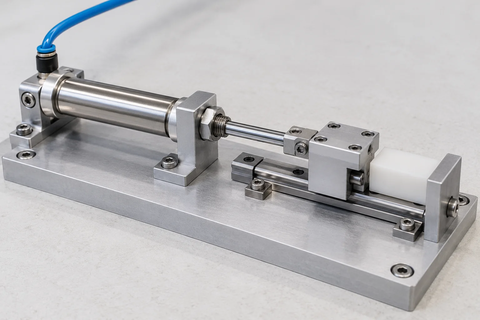
Check mounting access, rear-cover and rod-end clearance. Choose the return action and route the air connection outside the moving path.
New machine
Define the motion, load direction, return action and available space. Record any external guidance, required speed and position feedback.
Replacement
Record the full model, bore and stroke. Compare front and rear mounting, rod end, port thread and sensor details. Keep reference photos ready to share.
- Start with the installation envelope
- Use PB for ultra-small bores and MPE for very short single-acting motion. For larger mini-cylinder platforms, check body length, rear-cover layout and rod-end clearance together.
- Choose acting type before stroke
- A single-acting model uses a spring for the return direction and has its own stroke and pressure limits. Do not apply the double-acting stroke table to a spring-return model.
- Specify the cushioning suffix
- MI versus MIC, MF versus MFC, and MBL versus MBLC distinguish bumper and variable-cushion arrangements. MAC, MACD, MACJ and MAR also use variable cushioning. Match the complete code to the required end-stop behaviour.
- Check the bore-specific port
- The port changeover differs by platform. MG bore 20 uses M5, while MF bore 20 uses a pipe port. Fittings must follow the selected series table.
Check the details.
Prepare the requirement.
Use the new-machine and replacement checklists alongside the selected cylinder data.
Common questions.
When is MPE preferable to PB?
MPE and MPEF are single-acting micro cylinders with a short-stroke selection. PB provides a wider mix of acting and rod variants. Choose by the required return action, stroke, bore and mounting space.
Does a cushion suffix change selection?
Yes. MIC and MFC identify variable-cushion configurations in their platforms. Other suffixes identify double rods, adjustable strokes or single-acting models, so the full code matters.
Can one port adapter be used across all mini cylinders?
Check each bore and series. A bore used with M5 in one platform may use a pipe port in another. Confirm thread form as well as nominal port size.
How should a long-stroke mini cylinder be supported?
Supply the load direction, alignment and available external guidance when selecting the stroke. The stroke table does not establish allowable side load or resistance to bending.
Bring the cylinder
details together.
Record the complete series and variant, return action, bore and stroke. Add mounting, rod end, port thread, cushioning and load guidance, then quantity and schedule.
Create a mini-cylinder briefCopy or download your component requirements.
- Motion and code
- Series / variant / return action / bore / stroke
- Fit and air interface
- Mounting / rod end / port thread / cushioning
- Application and order
- Load direction / guidance / quantity / schedule