Rodless pneumatic
cylinders.
Magnetically coupled travel without an extending piston rod. Compare basic and guided platforms by load position, carriage guidance, coupling margin and stop duty.

Four rodless platforms.
Choose the guidance.
Compare the carriage and guide arrangement before setting bore and travel. Load position, coupling margin and end-stop duty belong in the same selection.
RMS Series
Basic, P and F versions with different bore and mounting choices. Confirm the version and any external load guidance before choosing travel.
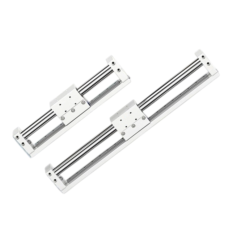
RMH Series
A linear-guided platform for a carried tool or fixture. Check load offset, mounting faces and bore-specific ports against the installation.
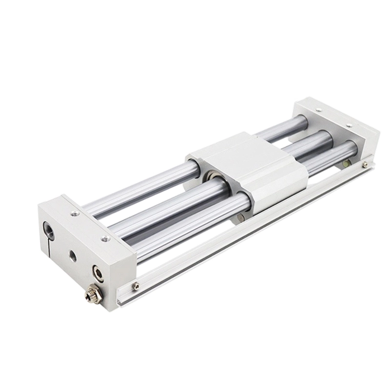
RMT Series
A guided carriage with adjustable-nut or option A shock-absorber cushioning. Review load position, position sensing and the required stop duty.

RMTL Series
A ball-bearing-guided format for the carried assembly. Confirm guide-load limits, position-sensing options and clearance at both ends of travel.
Guidance, coupling
and stop duty.
Start with the carried load and its centre of gravity. Choose the guidance and stopping arrangement before setting bore, stroke and position-sensing options.
| Series group | Guide and layout | What to confirm |
|---|---|---|
| RMS Series | Basic / P / F versions; external guidance as required | Match version, bore and mounting together. Provide suitable external guidance for lateral loads or rotation, and check magnetic-coupling margin. |
| RMH Series | Linear-guided carriage | Check the carried tool, load offset and mounting arrangement. Confirm guide-load limits separately from magnetic holding-force data. |
| RMT Series | Guided carriage; adjustable-nut or option A shock-absorber cushioning | Review acceleration, stopping duty and load position. Keep the cushioning code and position-sensing option with the complete model. |
| RMTL Series | Ball-bearing-guided carriage | Compare load mass and centre-of-gravity offset with the guide limits. Allow room for end stops, switches, fittings and service access. |
Safe holding force is a magnetic-coupling reference, not an allowable payload, guide-moment rating or safety brake. For RMS intermediate stopping, operating pressure must be ≤0.55 MPa with suitable end buffering; confirm the stopping method, load and coupling margin for the application.
Series-specific
technical data.
Compare operating conditions and model options with the stroke and port table for the same series. Keep version, bore, mounting and cushioning qualifiers with the complete model.
Safe holding force refers to magnetic coupling. Confirm permissible guide loads, moments and stopping duty separately. Position-sensing magnet options are distinct from the magnetic drive coupling.
RMS SeriesBasic / P / F versions · Version-specific bore and mounting
Scroll the table sideways to compare all series, bore, port, stroke and final-column details. Keyboard: focus the table area, then use the left and right arrow keys.
| Series | Acting | Bore (mm) | Port size | Listed standard strokes (mm) | Max. standard stroke (mm) |
|---|---|---|---|---|---|
| RMS Basic | Double acting | 10 | M5×0.8 | 50 100 150 200 250 300 | 1000 |
| RMS / RMSF / RMSP | Double acting | 16 | Confirm on model drawing | 50 100 150 200 250 300 350 400 450 500 | 1500 |
| RMS / RMSF / RMSP | Double acting | 20 | 1/8 | 50 100 150 200 250 300 350 400 450 500 600 700 750 800 900 1000 | 2000 |
| RMS / RMSF | Double acting | 25 | 1/8 | 50 100 150 200 250 300 350 400 450 500 600 700 750 800 900 1000 | 2500 |
| RMS / RMSF / RMSP | Double acting | 32 | 1/8 | 50 100 150 200 250 300 350 400 450 500 600 700 750 800 900 1000 | 3000 |
| RMS / RMSF | Double acting | 40 | 1/4 | 50 100 150 200 250 300 350 400 450 500 600 700 750 800 900 1000 | 3000 |
Confirm the complete RMS, RMSP or RMSF version and port thread. Bore 10 is listed for RMS Basic; P and F versions have different bore coverage.
For bore 16, confirm the RMS port on the selected model drawing. Basic, P and F have different bore coverage; listed maximum strokes do not establish the same travel or mounting fit across versions. RMSF40 has no FA mounting accessories.
RMH SeriesLinear guidance · Load and mounting confirmation
Scroll the table sideways to compare all series, bore, port, stroke and final-column details. Keyboard: focus the table area, then use the left and right arrow keys.
| Series | Acting | Bore (mm) | Port size | Listed standard strokes (mm) | Notes |
|---|---|---|---|---|---|
| RMH (Linear guide) | Double acting | 10 | M5×0.8 | 50 100 150 200 250 300 | Non-standard: consult |
| RMH (Linear guide) | Double acting | 16 | M5×0.8 | 50 100 150 200 250 300 350 400 450 500 | Non-standard: consult |
| RMH (Linear guide) | Double acting | 20 | 1/8 | 50 100 150 200 250 300 350 400 450 500 600 700 750 800 | Non-standard: consult |
| RMH (Linear guide) | Double acting | 25 | 1/8 | 50 100 150 200 250 300 350 400 450 500 600 700 750 800 | Non-standard: consult |
Stroke availability depends on the complete model, acting type and options. Confirm the configuration and mounting drawing before ordering.
RMT SeriesGuided carriage · Cushioning and position-sensing options
Scroll the table sideways to compare all series, bore, port, stroke and final-column details. Keyboard: focus the table area, then use the left and right arrow keys.
| Series | Acting | Bore (mm) | Port size | Listed standard strokes (mm) | Max. standard stroke (mm) |
|---|---|---|---|---|---|
| RMT (Guided) | Double acting | 16 | M5×0.8 | 50 100 150 200 250 300 350 400 450 500 | 750 |
| RMT (Guided) | Double acting | 20 | 1/8 | 50 100 150 200 250 300 350 400 450 500 600 700 750 800 | 1000 |
| RMT (Guided) | Double acting | 25 | 1/8 | 50 100 150 200 250 300 350 400 450 500 600 700 750 800 | 1500 |
| RMT (Guided) | Double acting | 32 | 1/8 | 50 100 150 200 250 300 350 400 450 500 600 700 750 800 | 1500 |
| RMT (Guided) | Double acting | 40 | 1/4 | 50 100 150 200 250 300 350 400 450 500 600 700 750 800 900 1000 | 1500 |
Stroke availability depends on the complete model, acting type and options. Confirm the configuration and mounting drawing before ordering.
RMTL SeriesBall-bearing guidance · Load offset and end clearance
Scroll the table sideways to compare all series, bore, port, stroke and final-column details. Keyboard: focus the table area, then use the left and right arrow keys.
| Series | Acting | Bore (mm) | Port size | Listed standard strokes (mm) | Max. standard stroke (mm) |
|---|---|---|---|---|---|
| RMTL (Ball bearing) | Double acting | 10 | M5×0.8 | 50 100 150 200 250 300 | 500 |
| RMTL (Ball bearing) | Double acting | 16 | M5×0.8 | 50 100 150 200 250 300 350 400 450 500 | 750 |
| RMTL (Ball bearing) | Double acting | 20 | 1/8 | 50 100 150 200 250 300 350 400 450 500 600 700 750 800 | 1000 |
| RMTL (Ball bearing) | Double acting | 25 | 1/8 | 50 100 150 200 250 300 350 400 450 500 600 700 750 800 | 1500 |
| RMTL (Ball bearing) | Double acting | 32 | 1/8 | 50 100 150 200 250 300 350 400 450 500 600 700 750 800 | 1500 |
| RMTL (Ball bearing) | Double acting | 40 | 1/4 | 50 100 150 200 250 300 350 400 450 500 600 700 750 800 900 1000 | 1500 |
Stroke availability depends on the complete model, acting type and options. Confirm the configuration and mounting drawing before ordering.
Rodless travel.
Plan the moving carriage.
Check the carried mass, load offset and travel envelope together. Include guidance, coupling margin and stopping duty in the installation design.

New machine
Provide load mass, centre-of-gravity offset, mounting orientation, effective travel and acceleration profile. Describe intermediate stops, end buffering and external guidance where required.
Replacement
Record the complete series and version, bore, stroke, mounting drawing, port thread, cushioning and position-sensing options. Keep reference photos ready to share.
- Choose guidance before bore
- Use RMS when suitable external guidance already exists. Compare RMH linear guidance, RMT guided carriage and RMTL ball-bearing guidance when the carriage must resist rotation or offset loads.
- Check coupling force separately
- Safe holding force is the magnetic coupling reference. It differs from guide-load capacity and must be considered with acceleration, shocks, orientation and mid-stroke stops.
- Plan travel and end clearance
- Select effective travel, then allow room for ports, switches, fittings and end-stop hardware. A rodless layout still needs a supported installation and service access.
- Specify cushioning and stop duty
- RMT and RMTL offer adjustable-nut or shock-absorber arrangements. For RMS mid-stroke stopping, include the pressure restriction and end buffering in the operating design.
Check the details.
Prepare the requirement.
Use the new-machine and replacement checklists alongside the selected rodless-cylinder data.
Common questions.
Is safe holding force the payload capacity?
No. It is the magnetic coupling reference between piston and carriage. Payload also depends on guidance, orientation, moment, acceleration and shocks.
Can RMS stop mid-stroke?
The RMS selection specifies operating pressure no higher than 0.55 MPa for mid-stroke stopping and requires buffering at the ends. Confirm the stopping method, coupling margin and load before selecting a circuit.
When should I choose a guided rodless version?
Choose guidance when tooling creates rotation, lateral force or an offset moment. Confirm the selected guide-load limits as well as bore and stroke.
Which RMS mounting bracket should I specify?
RMS lists non-bracket, LB and FA choices, with FA accessories excluded for RMSF40. Specify version, bore and bracket together and confirm the installation drawing.
Plan the carriage.
Define the requirement.
Record the full series and version, bore and stroke. Add load mass, centre-of-gravity offset, mounting orientation, acceleration, stopping duty, interfaces, quantity and schedule.
Create a rodless-cylinder briefCopy or download your component requirements.
- Series and travel
- Full code / version / bore / effective stroke
- Carriage and load
- Mass / load offset / orientation / guidance / stopping duty
- Interfaces and order
- Mounting / ports / cushioning / sensing / quantity / schedule