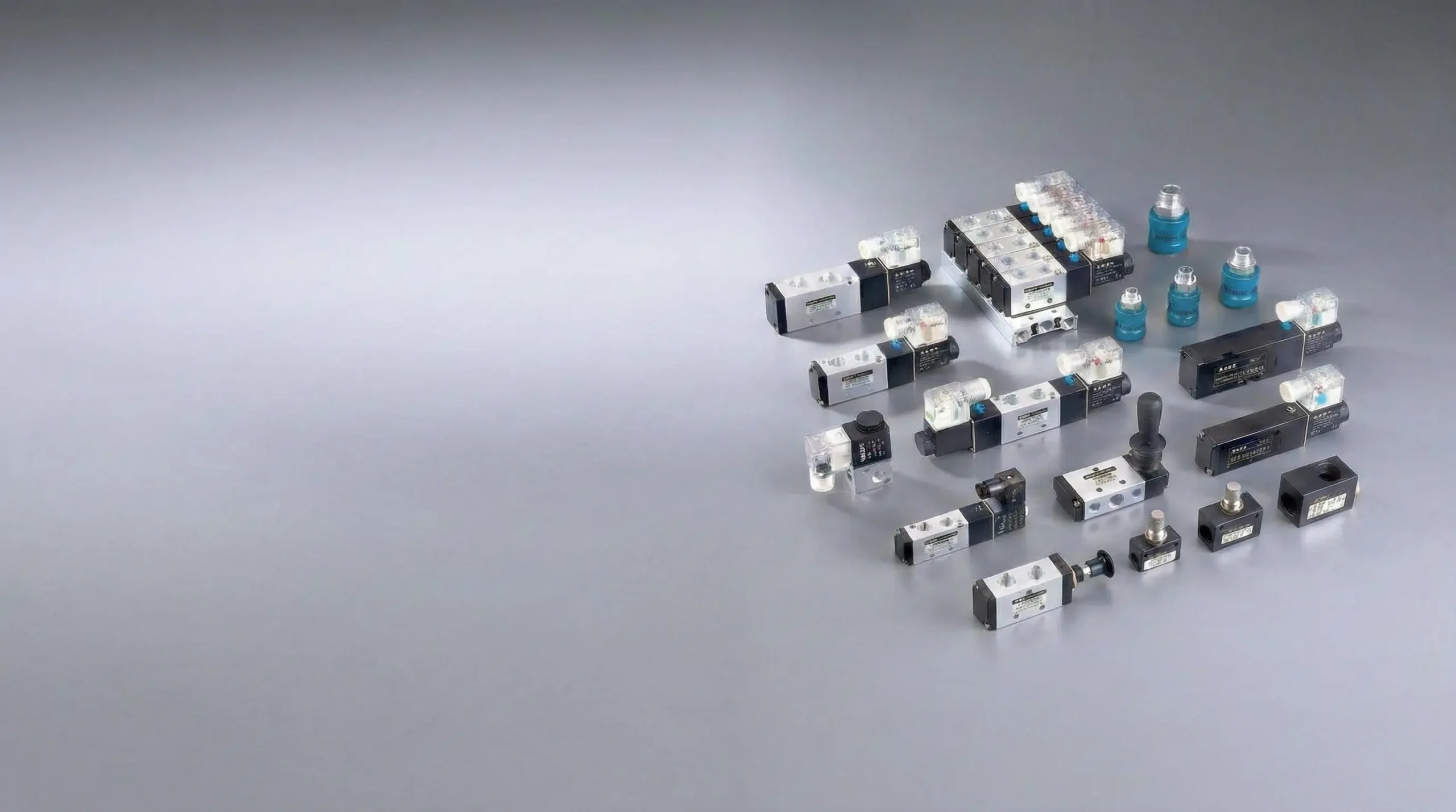
Pneumatic valves.
Control the circuit.
Directional, fluid, manual, mechanical and auxiliary valve ranges. Compare four categories and 25 series groups by circuit task, medium and control method.
Valve range · representative source arrangement
Four routes.
Start with the task.
Choose the category for the circuit task and medium, then compare the series. Electrical, pneumatic and local actuation options vary by platform.
Pneumatic Solenoid Valves
Directional valves for cylinder air circuits. Compare valve function, pilot-pressure needs, mounting and the selected coil supply.
Fluid Control Valves
Process-fluid isolation and pulse-valve platforms. Match the actual medium, body, seal and pressure differential to the selected model.
Manual Control Valves
Foot, lever, rotary, push-pull and slide formats. Check the operator action, valve symbol and return or detent behavior.
Mechanical & Auxiliary Valves
Limit valves, quick exhaust, check and shuttle valves, plus vacuum generation. Choose by circuit role and the required interfaces.
Match the circuit.
Then choose the control.
Category names describe both circuit tasks and actuation. A process-fluid valve may be electrically or pneumatically operated; auxiliary components perform different pneumatic functions.
| Route | Typical circuit role | What to confirm |
|---|---|---|
| Pneumatic solenoid | Switching pneumatic directional circuits | Valve symbol and rest or centre state, required flow, pilot pressure, coil voltage and mounting. Confirm the complete model and connector. |
| Fluid control | Process isolation or compressed-air pulse duty, depending on series | Actual medium, body and seals, temperature, inlet pressure and minimum pressure differential. For air-operated models, specify the separate control-air supply. |
| Manual control | Local operator control | Operator action, valve symbol, spring return or detent, port thread and panel or floor mounting. Guard and locking options vary by model. |
| Mechanical & auxiliary | Position switching, check or shuttle logic, local exhaust or vacuum generation | Choose the circuit function first. Then check mechanical travel and mounting, or the exhaust, one-way, shuttle or vacuum requirements of the selected component. |
A matching port size is only one interface check. Compare the complete model, valve symbol, mounting and operating limits before selecting a replacement.
From circuit task
to installation details.
Bring the medium, pressure conditions and valve function together. Then confirm the control supply, connections and installation drawing for the selected model.

New machine
Provide the circuit task, required valve function and actual medium. Include flow demand, inlet and outlet conditions, operating temperature and the required rest or centre state.
Replacement
Record the full model and valve symbol. Keep photos of the label, port layout, mounting and electrical or pneumatic control connections ready to share.
- Medium and service
- Actual fluid and composition, operating temperature and the required body and seal compatibility.
- Pressure and flow
- Minimum and maximum inlet and outlet pressures, start-up pressure differential and selected-medium flow at the permitted pressure drop.
- Circuit function
- Valve symbol, rest or centre state and return or detent behavior. For auxiliary parts, specify exhaust, logic, one-way or vacuum duty.
- Control and mounting
- Coil supply and connector for electrical operation, or separate pilot-air conditions for pneumatic operation. Confirm mounting and connections.
- Ports
- Thread standard and connection size, not nominal size alone.
- Pilot supply
- Required pressure and circuit conditions for the exact model.
- Service access
- Space for fittings, tube bends, wiring and operator travel.
Copy or download the requirements for your next discussion.
All 25 series groups.
The range in one place.
Open a category to compare its series roles and available data. Photos are source range references; shared manual-valve photos do not identify every variant.
Pneumatic Solenoid Valves4 series groups
 4V Series
Pilot-operated directional valve platform covering common cylinder-control functions.
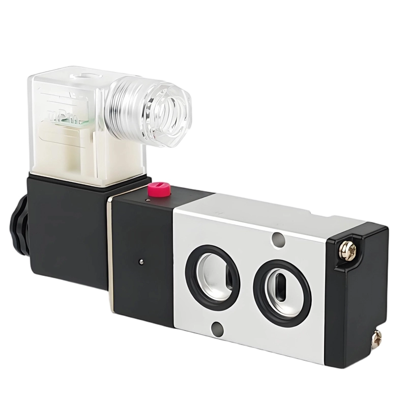 4M Series
Compact directional valve platform, including actuator-mounting configurations. Confirm the interface drawing.
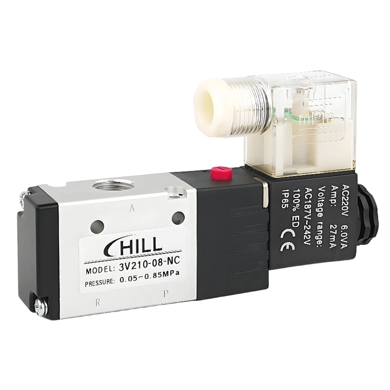 3V Series
Compact 3/2 valve platform for single-acting and pilot-control circuits.
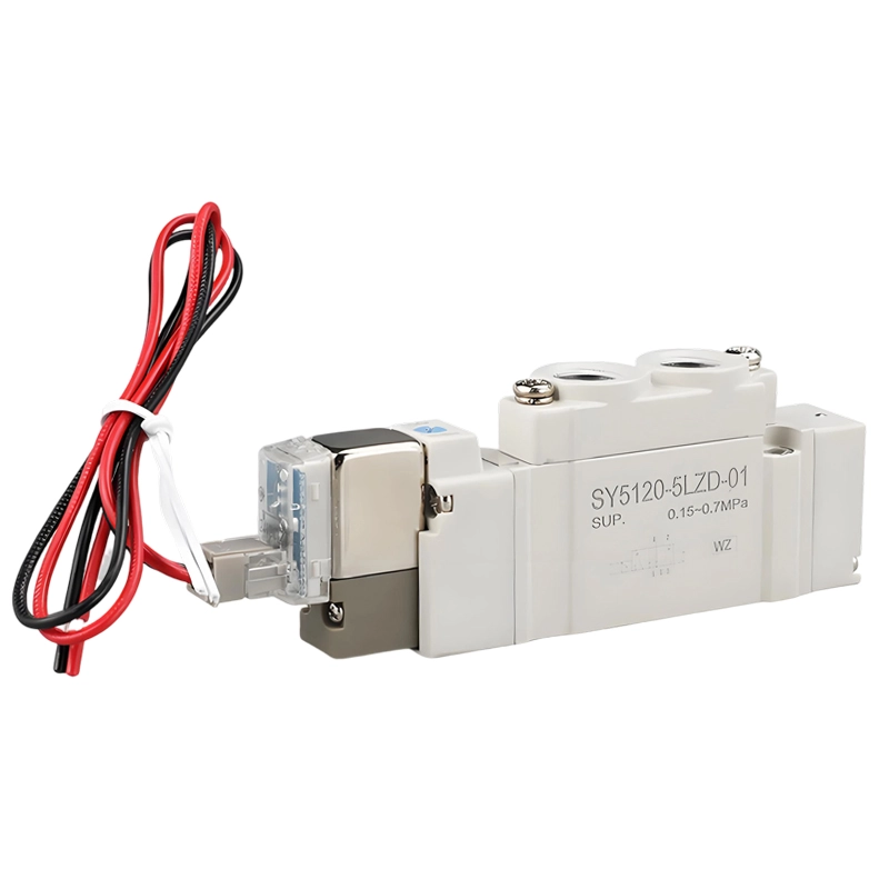 SY Series
Manifold-oriented valve platform for grouped multi-actuator control.
Fluid Control Valves6 series groups
 2J Series
Air-operated angle-seat valve platform for process-fluid isolation.
 US Series
Steam solenoid valve platform. Check temperature, pressure differential and installation requirements.
 2W Series
Solenoid valve platform for general fluid control. Confirm the operating principle, body and seal combination for the selected model.
 2Q Series
Air-operated fluid valve platform with a separate pneumatic control supply.
 Q22HD Series
Compact air-control valve platform for process circuits.
 DMF Series
Pulse valve platform for intermittent compressed-air discharge.
Manual Control Valves7 series groups
 4F Series
Foot-pedal valve platform with guard and locking options according to model.
Shared source range photo- 3F / 3FM Series
Foot-operated valve platforms for compact local-control circuits.
Shared source range photo  4H Series
Hand-lever directional valves for local actuator control.
 4HV Series
Rotary hand-control valve platform.
 3L Series
Push-pull valve platform for 3/2 control circuits.
Shared source range photo- 4L Series
Push-pull valve platform for double-acting cylinder circuits.
Shared source range photo  HSV Series
Hand-slide valve platform for local air-line operation.
Mechanical & Auxiliary Valves8 series groups

- QE Series
Quick-exhaust valves that discharge air locally near the actuator.
- KA Series
Check valves for one-way pneumatic flow.
- ST Series
Shuttle valves for pneumatic OR logic.
- CV Series
Single-stage vacuum generators for suction circuits.
- MV / MOV Series
Mechanical limit valves with roller, plunger and other actuator choices.
- VM Series
Compact mechanical valves with model-dependent inlet and mounting arrangements.
- S3 / CM3 Series
Button-operated valves for panel and local control.
- M3 / M5 Series
Micro mechanical valves for space-limited mechanisms.
Technical references.
Prepare the right details.
Review the category data and selection checklists alongside the valve symbol, operating conditions and installation drawing for your chosen model.
Common questions.
Are all four categories electrically operated?
The categories describe both circuit tasks and actuation. Fluid-control series include electrical and air-operated platforms. Manual and mechanical valves use local operators, while auxiliary components provide functions such as exhaust, check, shuttle logic or vacuum generation.
Does matching the port thread confirm a replacement?
Compare the complete model, valve symbol, rest or centre state, mounting dimensions and operating limits. Also check flow, pilot-pressure requirements and the control supply or operator arrangement for the selected variant.
What should I check for fluid-control service?
Specify the actual medium and composition, temperature, inlet and outlet pressures and start-up pressure differential. Confirm the selected model’s body, seals and operating principle. Air-operated models also need separate control-air conditions.
Bring the valve
requirements together.
Start with the circuit task, medium and selected series. Add the valve function, pressure and flow conditions, control method, connections and quantity for your next discussion.
Create a valve briefCopy or download your component requirements.
- Series and circuit
- Complete model / valve symbol / control method
- Operating conditions
- Medium / temperature / inlet and outlet pressure / flow
- Installation and order
- Connections / mounting / quantity / timing / destination