
SDA Series Compact Pneumatic Cylinders
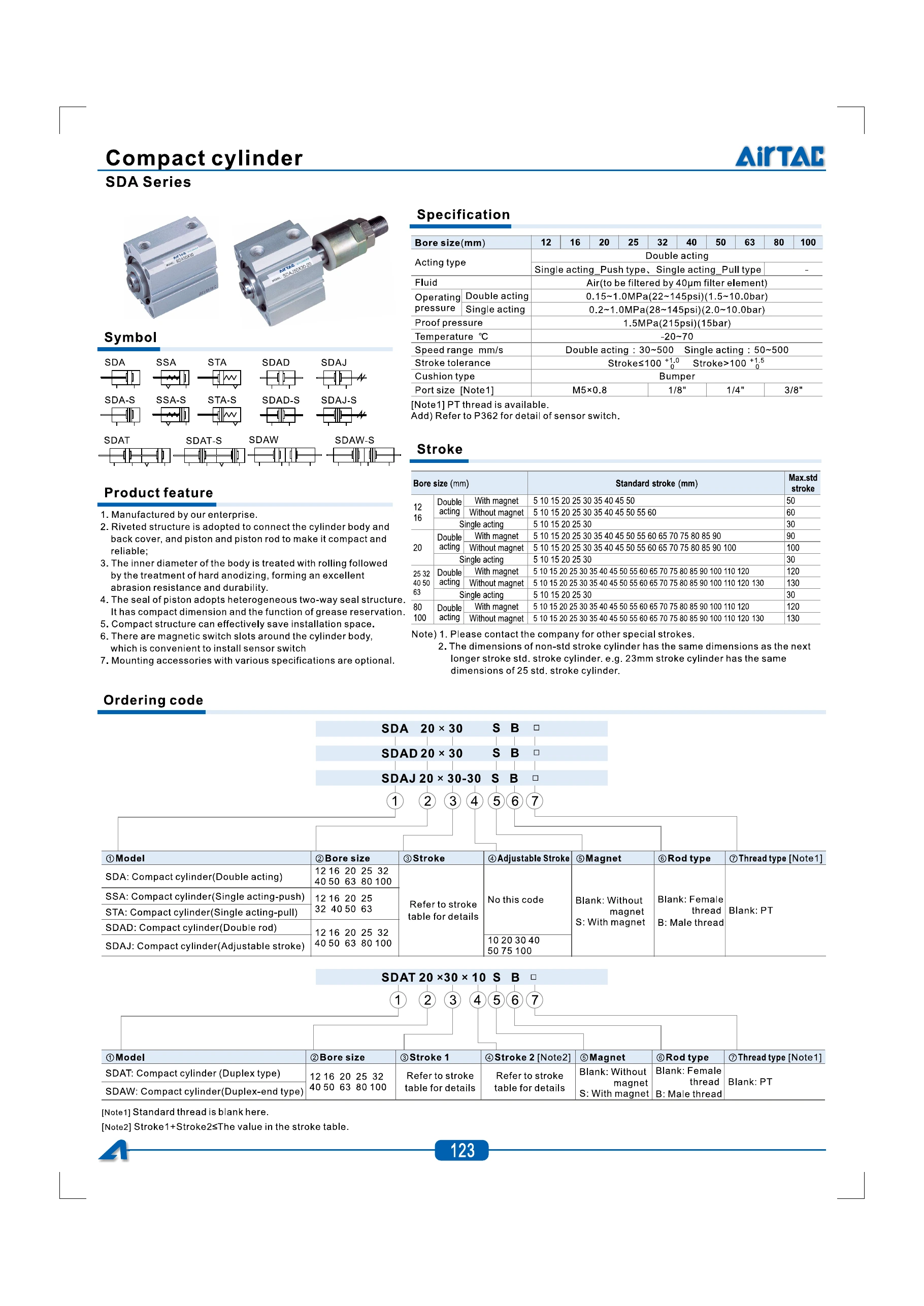
A short-body cylinder platform with sensor grooves and female- or male-threaded rod options. Compare SDA double acting, SSA push and STA pull single acting, plus double-rod, adjustable-stroke and duplex arrangements using their own dimensions.
- Double-acting bore range
- 12–100 mm
- SSA / STA single-acting bores
- 12–63 mm
- Cushioning
- Bumper
Match the acting type, magnet and standard stroke.
The official 2024 file separates double- and single-acting conditions. Magnet selection changes standard-stroke limits and the A/AC dimensions; 80/100 mm bores are listed for double acting. Confirm the actual supplied configuration against the matching reference.
| Parameter | Catalog reference |
|---|---|
| Acting types | Double acting; single-acting push or pull for the documented smaller bores |
| Working medium | Air filtered through a 40 μm element |
| Double-acting operating pressure | 0.15–1.0 MPa |
| Single-acting operating pressure | 0.2–1.0 MPa |
| Proof pressure | 1.5 MPa |
| Standard temperature | −20 to +70 °C |
| Double-acting speed | 30–500 mm/s |
| Single-acting speed | 50–500 mm/s |
| Cushion type | Bumper |
| Stroke tolerance, stroke ≤100 mm | +1.0 / 0 mm |
| Stroke tolerance, stroke >100 mm | +1.5 / 0 mm |
These are the conditions in the 2024 official file, subject to the documented model and bore range. Proof pressure is a test value. Bumper cushioning is not adjustable air cushioning.
| Bore (mm) | Double acting | SSA / STA single acting | Air connection |
|---|---|---|---|
| 12 | Listed | Listed | M5 × 0.8 |
| 16 | Listed | Listed | M5 × 0.8 |
| 20 | Listed | Listed | M5 × 0.8 |
| 25 | Listed | Listed | M5 × 0.8 |
| 32 | Listed | Listed | 1/8″ |
| 40 | Listed | Listed | 1/8″ |
| 50 | Listed | Listed | 1/4″ |
| 63 | Listed | Listed | 1/4″ |
| 80 | Listed | Not listed | 3/8″ |
| 100 | Listed | Not listed | 3/8″ |
M5 air connections are metric. The ordering reference lists blank as PT for pipe threads; confirm the actual supplied connection and thread before ordering.
Scroll the table horizontally to compare all columns.
| Bore range (mm) | Acting / magnet | Listed standard strokes (mm) | Maximum standard stroke (mm) |
|---|---|---|---|
| 12 / 16 | Double acting, with magnet | 5 10 15 20 25 30 35 40 45 50 | 50 |
| 12 / 16 | Double acting, without magnet | 5 10 15 20 25 30 35 40 45 50 55 60 | 60 |
| 12 / 16 | Single acting | 5 10 15 20 25 30 | 30 |
| 20 | Double acting, with magnet | 5 10 15 20 25 30 35 40 45 50 55 60 65 70 75 80 85 90 | 90 |
| 20 | Double acting, without magnet | 5 10 15 20 25 30 35 40 45 50 55 60 65 70 75 80 85 90 100 | 100 |
| 20 | Single acting | 5 10 15 20 25 30 | 30 |
| 25 / 32 / 40 / 50 / 63 | Double acting, with magnet | 5 10 15 20 25 30 35 40 45 50 55 60 65 70 75 80 85 90 100 110 120 | 120 |
| 25 / 32 / 40 / 50 / 63 | Double acting, without magnet | 5 10 15 20 25 30 35 40 45 50 55 60 65 70 75 80 85 90 100 110 120 130 | 130 |
| 25 / 32 / 40 / 50 / 63 | Single acting | 5 10 15 20 25 30 | 30 |
| 80 / 100 | Double acting, with magnet | 5 10 15 20 25 30 35 40 45 50 55 60 65 70 75 80 85 90 100 110 120 | 120 |
| 80 / 100 | Double acting, without magnet | 5 10 15 20 25 30 35 40 45 50 55 60 65 70 75 80 85 90 100 110 120 130 | 130 |
Maximum standard stroke is the catalog column heading, not a verified absolute travel limit. Other strokes require confirmation. The source states that a non-standard stroke uses the dimensions of the next longer standard stroke, for example 23 mm uses the 25 mm envelope. Do not interpolate an unlisted stroke or apply a single-acting range to 80/100 mm.
Scroll the table horizontally to compare all columns.
Choose one arrangement and complete its ordering fields.
SDA, SSA, STA, SDAD and SDAJ use the main code layout. SDAT and SDAW need two stroke fields and their own travel drawings. Use the blank PT pipe-thread reference only where the selected connection is a pipe thread.
Documented configurations
| Code | Arrangement | Documented bore range (mm) |
|---|---|---|
| SDA | Double acting, single rod | 12–100 |
| SSA | Single acting, push | 12–63 |
| STA | Single acting, pull | 12–63 |
| SDAD | Double rod | 12–100 |
| SDAJ | Adjustable stroke | 12–100 |
| SDAT | Duplex type, two stroke fields | 12–100 |
| SDAW | Duplex-end type, two stroke fields | 12–100 |
Select the arrangement first. The same bore does not establish the same body length, rod projection, air-port layout or travel envelope.
Scroll the table horizontally to compare all columns.
Common ordering fields
| Field | Catalog choices |
|---|---|
| Model | SDA / SSA / STA / SDAD / SDAJ, or the separate SDAT / SDAW arrangement |
| Bore | 12 16 20 25 32 40 50 63 80 100; SSA / STA stop at 63 |
| Stroke | Use the model, bore and magnet-specific standard-stroke table |
| Adjustable stroke | SDAJ: 10 20 30 40 50 75 100; other listed models have no adjustable-stroke field |
| Magnet | Blank: without magnet; S: with magnet |
| Rod end | Blank: female thread; B: male thread |
| Pipe-thread code | Blank: PT in this reference |
M5 air connections remain metric. No G, Rc or NPT ordering option is established by this reference. Confirm the offered complete code, sensor requirements and actual thread before ordering.
Scroll the table horizontally to compare all columns.
SDAT and SDAW stroke fields
| Field | Catalog requirement |
|---|---|
| Stroke 1 | Specify separately from stroke 2 |
| Stroke 2 | Specify separately from stroke 1 |
| Combined stroke limit | Stroke 1 + stroke 2 ≤ the value in the standard-stroke table |
The SDAT example contains two strokes separated by ×. Use the matching SDAT or SDAW drawing: their overall-length formulas and air-port arrangements differ.
Scroll the table horizontally to compare all columns.
Internal material reference
| Part | Material / bore qualification |
|---|---|
| Back cover | No (12 / 16 mm); aluminium alloy for other bores |
| Bumper | NBR |
| Piston | Brass for 12 / 16 mm; aluminium alloy for other bores |
| Piston seal | NBR |
| Piston rod | Carbon steel with 20 μm chrome plating |
| Body | Aluminium alloy |
| Front cover | Aluminium alloy |
| O-ring | NBR |
| C clip | Spring steel |
| Front cover packing | NBR |
| Piston nut | Carbon steel |
| Bushing | No (12–32 mm); wear-resistant material for other bores |
The source labels this as a structure/material reference based on a particular bore and requires a bore-specific sheet for confirmation. The listed materials do not establish every offered configuration or an independent compliance rating.
Scroll the table horizontally to compare all columns.
SDA specifications, stroke limits and ordering codes
Use the dimensions for the selected acting and rod arrangement.
Dimensions are in millimetres unless a thread is identified. The base SDA, SSA/STA, SDAD/SDAJ and SDAT/SDAW references have different lengths, rod projections and port arrangements. Select the magnet and stroke-dependent columns before checking the complete mounting and travel envelope. Open the matching model group to compare its complete dimension tables.
SDA base and rod-end dimensions
| Bore (mm) | A, no magnet | AC, no magnet | A, with magnet | AC, with magnet | AB | □B | BA | Rod ØD | DA | Female rod E | EA |
|---|---|---|---|---|---|---|---|---|---|---|---|
| 12 | 22 | 17 | 32 | 27 | 5 | 25 | — | 6 | 4 | M3 × 0.5 | 6 |
| 16 | 24 | 18.5 | 34 | 28.5 | 5.5 | 29 | — | 6 | 4 | M3 × 0.5 | 6 |
| 20 | 25 | 19.5 | 35 | 29.5 | 5.5 | 34 | 36 | 8 | 4 | M4 × 0.7 | 8 |
| 25 | 27 | 21 | 37 | 31 | 6 | 40 | 42 | 10 | 4 | M5 × 0.8 | 10 |
| 32 | 31.5 | 24.5 | 41.5 | 34.5 | 7 | 44 | 50 | 12 | 4.5 | M6 × 1.0 | 12 |
| 40 | 33 | 26 | 43 | 36 | 7 | 52 | 58.5 | 16 | 4 | M8 × 1.25 | 12 |
| 50 | 37 | 28 | 47 | 38 | 9 | 62 | 71.5 | 20 | 5 | M10 × 1.5 | 15 |
| 63 | 41 | 32 | 51 | 42 | 9 | 75 | 84.5 | 20 | 5 | M10 × 1.5 | 15 |
| 80 | 52 | 41 | 62 | 51 | 11 | 94 | 104 | 25 | 6 | M14 × 1.5 | 20 |
| 100 | 63 | 51 | 73 | 61 | 12 | 114 | 124 | 32 | 7 | M18 × 1.5 | 20 |
SDA overall length is A + stroke; the body-related length is AC + stroke. Use the magnet-specific A/AC pair. All dimensions are mm unless a thread is identified; a dash means no value is listed.
Scroll the table horizontally to compare all columns.
| Bore (mm) | H | J | JA | K: thread / through-hole Ø | KA | KB | ØM | MA | Port P | PA, St=5 | PA, St>5 | PB, St=5 | PB, St>5 | T |
|---|---|---|---|---|---|---|---|---|---|---|---|---|---|---|
| 12 | 5 | 6.5 | 4.5 | M5 × 0.8 / Ø4.2 | 12 | 16.3 | 10.2 | 1 | M5 × 0.8 | 7.5 | 7.5 | 5 | 5 | 23 |
| 16 | 5 | 6.5 | 4.5 | M5 × 0.8 / Ø4.2 | 12 | 19.8 | 11 | 1.5 | M5 × 0.8 | 8 | 8 | 5 | 5.5 | 28 |
| 20 | 6 | 6.5 | 4.5 | M5 × 0.8 / Ø4.2 | 14 | 24 | 13 | 1.5 | M5 × 0.8 | 8 | 9 | 5.5 | 5.5 | — |
| 25 | 8 | 8.2 | 5.5 | M6 × 1.0 / Ø5.2 | 15 | 28 | 17 | 2 | M5 × 0.8 | 9 | 9 | 5.5 | 5.5 | — |
| 32 | 10 | 8.2 | 5.5 | M6 × 1.0 / Ø5.2 | 16 | 34 | 22 | 2.5 | 1/8″ | 9 | 9 | 6.5 | 9 | — |
| 40 | 14 | 10.5 | 6.5 | M8 × 1.25 / Ø6.7 | 20 | 40 | 28 | 3 | 1/8″ | 9.5 | 9.5 | 7.5 | 7.5 | — |
| 50 | 17 | 10.5 | 6.5 | M8 × 1.25 / Ø6.7 | 25 | 48 | 38 | 4 | 1/4″ | 8 | 10.5 | 8 | 10.5 | — |
| 63 | 17 | 10.5 | 6.5 | M8 × 1.25 / Ø6.7 | 25 | 60 | 40 | 4 | 1/4″ | 9.5 | 12 | 9.5 | 11 | — |
| 80 | 22 | 17 | 11 | M12 × 1.75 / Ø10.4 | 25 | 74 | 45 | 5 | 3/8″ | 11.5 | 14.5 | 11.5 | 14.5 | — |
| 100 | 27 | 19 | 13 | M14 × 2.0 / Ø12.4 | 30 | 90 | 55 | 5 | 3/8″ | 16 | 20.5 | 16 | 20.5 | — |
St means stroke in mm. PA/PB use the printed 5 mm / greater-than-5 mm distinction. Check the drawing for hole count and depth; a thread designation alone does not define the complete mounting hole.
Scroll the table horizontally to compare all columns.
| Bore (mm) | AB | ØD | DA | Male rod E | EA | EB | F | FA | H | ØM | MA, SDAD / SDAJ | MA, others |
|---|---|---|---|---|---|---|---|---|---|---|---|---|
| 12 | 17 | 6 | 16 | M5 × 0.8 | 10 | 12 | 8 | 4 | 5 | 10.2 | 1 | 1 |
| 16 | 17.5 | 6 | 16 | M5 × 0.8 | 10 | 12 | 8 | 4 | 5 | 11 | 1.5 | 1.5 |
| 20 | 20.5 | 8 | 19 | M6 × 1.0 | 13 | 15 | 10 | 5 | 6 | 13 | 1.5 | 1.5 |
| 25 | 23 | 10 | 21 | M8 × 1.25 | 15 | 17 | 12 | 6 | 8 | 17 | 2 | 2 |
| 32 | 25 | 12 | 22 | M10 × 1.25 | 15 | 18 | 17 | 6 | 10 | 22 | 3 | 2.5 |
| 40 | 35 | 16 | 32 | M14 × 1.5 | 25 | 27.5 | 19 | 8 | 14 | 28 | 3 | 3 |
| 50 | 36.5 | 20 | 32.5 | M18 × 1.5 | 25.5 | 27.5 | 27 | 11 | 17 | 38 | 4 | 4 |
| 63 | 37.5 | 20 | 33.5 | M18 × 1.5 | 26 | 28 | 27 | 11 | 17 | 40 | 4 | 4 |
| 80 | 44 | 25 | 39 | M22 × 1.5 | 30 | 33 | 32 | 13 | 22 | 45 | 5 | 5 |
| 100 | 50 | 32 | 45 | M26 × 1.5 | 35 | 38 | 36 | 13 | 27 | 55 | 5 | 5 |
These values belong to the male rod drawing. Pull-type labels add the pull stroke to AB and DA. At 32 mm bore MA is 3 for SDAD/SDAJ and 2.5 for the other arrangements in this table.
Scroll the table horizontally to compare all columns.
SSA / STA single-acting dimensions
| Bore (mm) | A no magnet, St≤10 | A no magnet, St>10 | A with magnet, St≤10 | A with magnet, St>10 | AB | AC no magnet, St≤10 | AC no magnet, St>10 | AC with magnet, St≤10 | AC with magnet, St>10 | □B | BA |
|---|---|---|---|---|---|---|---|---|---|---|---|
| 12 | 32 | 42 | 42 | 52 | 5 | 27 | 37 | 37 | 47 | 25 | — |
| 16 | 34 | 44 | 44 | 54 | 5.5 | 28.5 | 38.5 | 38.5 | 48.5 | 29 | — |
| 20 | 35 | 45 | 45 | 55 | 5.5 | 29.5 | 39.5 | 39.5 | 49.5 | 34 | 36 |
| 25 | 37 | 47 | 47 | 57 | 6 | 31 | 41 | 41 | 51 | 40 | 42 |
| 32 | 41.5 | 51.5 | 51.5 | 61.5 | 7 | 34.5 | 44.5 | 44.5 | 54.5 | 44 | 50 |
| 40 | 43 | 53 | 53 | 63 | 7 | 36 | 46 | 46 | 56 | 52 | 58.5 |
| 50 | 47 | 57 | 57 | 67 | 9 | 38 | 48 | 48 | 58 | 62 | 71.5 |
| 63 | 51 | 61 | 61 | 71 | 9 | 42 | 52 | 52 | 62 | 75 | 84.5 |
SSA overall length is A + stroke. STA overall length is A + 2 × stroke; its rod-side labels include AB + stroke and DA + stroke. Select the correct ≤10 / >10 mm A/AC pair; the 12–63 mm range does not extend to 80/100.
Scroll the table horizontally to compare all columns.
| Bore (mm) | ØD | DA | Female rod E | EA | H | J | JA | K: thread / through-hole Ø | KA | KB | ØM | MA | Port P | PA | PB | T |
|---|---|---|---|---|---|---|---|---|---|---|---|---|---|---|---|---|
| 12 | 6 | 4 | M3 × 0.5 | 6 | 5 | 6.5 | 4.5 | M5 × 0.8 / Ø4.2 | 12 | 16.3 | 10.2 | 1 | M5 × 0.8 | 7.5 | 5 | 23 |
| 16 | 6 | 4 | M3 × 0.5 | 6 | 5 | 6.5 | 4.5 | M5 × 0.8 / Ø4.2 | 12 | 19.8 | 11 | 1.5 | M5 × 0.8 | 8 | 5.5 | 28 |
| 20 | 8 | 4 | M4 × 0.7 | 8 | 6 | 6.5 | 4.5 | M5 × 0.8 / Ø4.2 | 14 | 24 | 13 | 1.5 | M5 × 0.8 | 9 | 5.5 | — |
| 25 | 10 | 4 | M5 × 0.8 | 10 | 8 | 8.2 | 5.5 | M6 × 1.0 / Ø5.2 | 15 | 28 | 17 | 2 | M5 × 0.8 | 9 | 5.5 | — |
| 32 | 12 | 4 | M6 × 1.0 | 12 | 10 | 8.2 | 5.5 | M6 × 1.0 / Ø5.2 | 16 | 34 | 22 | 2.4 | 1/8″ | 9 | 9 | — |
| 40 | 16 | 4 | M8 × 1.25 | 12 | 14 | 10.5 | 6.5 | M8 × 1.25 / Ø6.7 | 20 | 40 | 28 | 3 | 1/8″ | 9.5 | 7.5 | — |
| 50 | 20 | 5 | M10 × 1.5 | 15 | 17 | 10.5 | 6.5 | M8 × 1.25 / Ø6.7 | 25 | 48 | 38 | 4 | 1/4″ | 10.5 | 10.5 | — |
| 63 | 20 | 5 | M10 × 1.5 | 15 | 17 | 10.5 | 6.5 | M8 × 1.25 / Ø6.7 | 25 | 60 | 40 | 4 | 1/4″ | 12 | 11 | — |
At 32 mm bore this table prints MA = 2.4; it is preserved separately from the SDA base table. The source refers to printed p.124 for male rod-end dimensions.
Scroll the table horizontally to compare all columns.
SDAD double-rod dimensions
| Bore (mm) | A no magnet | A with magnet | AB | AC no magnet | AC with magnet | DA | Female rod E | ØM | MA |
|---|---|---|---|---|---|---|---|---|---|
| 12 | 27 | 37 | 5 | 17 | 27 | 4 | M3 × 0.5 | 10.2 | 1 |
| 16 | 29.5 | 39.5 | 5.5 | 18.5 | 28.5 | 4 | M3 × 0.5 | 11 | 1.5 |
| 20 | 30.5 | 40.5 | 5.5 | 19.5 | 29.5 | 4 | M4 × 0.7 | 15 | 1.5 |
| 25 | 33 | 43 | 6 | 21 | 31 | 4 | M5 × 0.8 | 17 | 2 |
| 32 | 38.5 | 48.5 | 7 | 24.5 | 34.5 | 4 | M6 × 1.0 | 22 | 3 |
| 40 | 40 | 50 | 7 | 26 | 36 | 4 | M8 × 1.25 | 28 | 3 |
| 50 | 46 | 56 | 9 | 28 | 38 | 5 | M10 × 1.5 | 38 | 4 |
| 63 | 50 | 60 | 9 | 32 | 42 | 5 | M10 × 1.5 | 40 | 4 |
| 80 | 63 | 73 | 11 | 41 | 51 | 6 | M14 × 1.5 | 45 | 5 |
| 100 | 75 | 85 | 12 | 51 | 61 | 7 | M18 × 1.5 | 55 | 5 |
SDAD overall length is A + 2 × stroke. Unmarked dimensions follow the SDA standard drawing, as explicitly stated in the source; the male rod reference is printed p.124.
Scroll the table horizontally to compare all columns.
| Bore (mm) | EA, St≤10 | EA, St>10 | EA, St<20 | EA, St≥20 | EA, St<15 | EA, St≥15 | PA, St=5 | PA, St>5 |
|---|---|---|---|---|---|---|---|---|
| 12 | 6 | 6 | — | — | — | — | 5.5 | 6.3 |
| 16 | 6 | 6 | — | — | — | — | 6.5 | 7.3 |
| 20 | 8 (6.5 for St=5) | 8 (6.5 for St=5) | — | — | — | — | 7.5 | 7.5 |
| 25 | 10 (7 for St=5) | 10 (7 for St=5) | — | — | — | — | 8 | 8 |
| 32 | 8 | 12 | — | — | — | — | 8 | 9 |
| 40 | 8 | 12 | — | — | — | — | 8 | 10 |
| 50 | — | — | 8 | 15 | — | — | 8 | 10.5 |
| 63 | — | — | 10 | 15 | — | — | 9.5 | 11.8 |
| 80 | — | — | 13 | 20 | — | — | 11.5 | 14.5 |
| 100 | — | — | — | — | 18 | 20 | 16 | 20.5 |
The printed merged EA cells for 20/25 mm cover both ≤10 and >10 columns; they are repeated here for readability, including the 5 mm exceptions. Other EA columns apply only where a value is printed.
Scroll the table horizontally to compare all columns.
SDAJ adjustable-stroke dimensions
| Bore (mm) | A no magnet | A with magnet | AB | AC no magnet | AC with magnet | AD | Female rod E | FA | ØM | MA |
|---|---|---|---|---|---|---|---|---|---|---|
| 12 | 40 | 50 | 5 | 17 | 27 | 17 | M3 × 0.5 | 4 | 10.2 | 1 |
| 16 | 42.5 | 52.5 | 5.5 | 18.5 | 28.5 | 17 | M3 × 0.5 | 4 | 11 | 1.5 |
| 20 | 47.5 | 57.5 | 5.5 | 19.5 | 29.5 | 21 | M4 × 0.7 | 5 | 15 | 1.5 |
| 25 | 54 | 64 | 6 | 21 | 31 | 25 | M5 × 0.8 | 6 | 17 | 2 |
| 32 | 61.5 | 71.5 | 7 | 24.5 | 34.5 | 27 | M6 × 1.0 | 6 | 22 | 3 |
| 40 | 64 | 74 | 7 | 26 | 36 | 28 | M8 × 1.25 | 7 | 28 | 3 |
| 50 | 70 | 80 | 9 | 28 | 38 | 29 | M10 × 1.5 | 8 | 38 | 4 |
| 63 | 74 | 84 | 9 | 32 | 42 | 29 | M10 × 1.5 | 8 | 40 | 4 |
| 80 | 92.5 | 102.5 | 11 | 41 | 51 | 35.5 | M14 × 1.5 | 10 | 45 | 5 |
| 100 | 110.5 | 120.5 | 12 | 51 | 61 | 42.5 | M18 × 1.5 | 13.5 | 55 | 5 |
SDAJ overall length is A + 2 × stroke + adjustable stroke. The adjustment-side label is AD + adjustable stroke. Unmarked dimensions follow the SDA standard drawing only as noted in the source.
Scroll the table horizontally to compare all columns.
| Bore (mm) | EA, St≤10 | EA, St>10 | EA, St<20 | EA, St≥20 | EA, St<15 | EA, St≥15 | PA, St=5 | PA, St>5 | Adjustment thread R |
|---|---|---|---|---|---|---|---|---|---|
| 12 | 6 | 6 | — | — | — | — | 5.5 | 6.3 | M5 × 0.8 |
| 16 | 6 | 6 | — | — | — | — | 6.5 | 7.3 | M5 × 0.8 |
| 20 | 8 (6.5 for St=5) | 8 (6.5 for St=5) | — | — | — | — | 7.5 | 7.5 | M6 × 1.0 |
| 25 | 10 (7 for St=5) | 10 (7 for St=5) | — | — | — | — | 8 | 8 | M8 × 1.25 |
| 32 | 8 | 12 | — | — | — | — | 8 | 9 | M10 × 1.25 |
| 40 | 8 | 12 | — | — | — | — | 8 | 10 | M12 × 1.25 |
| 50 | — | — | 8 | 15 | — | — | 8 | 10.5 | M16 × 1.5 |
| 63 | — | — | 10 | 15 | — | — | 9.5 | 11.8 | M16 × 1.5 |
| 80 | — | — | 13 | 20 | — | — | 11.5 | 14.5 | M20 × 1.5 |
| 100 | — | — | — | — | 18 | 20 | 16 | 20.5 | M27 × 2.0 |
EA merged values and 5 mm exceptions follow the SDAD/SDAJ printed tables. R is the adjustment thread, not the female piston-rod thread E.
Scroll the table horizontally to compare all columns.
SDAT duplex dimensions
| Bore (mm) | A no magnet | AC no magnet | AD no magnet | A with magnet | AC with magnet | AD with magnet | AB | □B | BA | ØD | DA |
|---|---|---|---|---|---|---|---|---|---|---|---|
| 12 | 39 | 34 | 17 | 59 | 54 | 27 | 5 | 25 | — | 6 | 4 |
| 16 | 42.5 | 37 | 18.5 | 62.5 | 57 | 28.5 | 5.5 | 29 | — | 6 | 4 |
| 20 | 44.5 | 39 | 19.5 | 64.5 | 59 | 29.5 | 5.5 | 34 | 36 | 8 | 4 |
| 25 | 48 | 42 | 21 | 68 | 62 | 31 | 6 | 40 | 42 | 10 | 4 |
| 32 | 56 | 49 | 24.5 | 76 | 69 | 34.5 | 7 | 44 | 50 | 12 | 4 |
| 40 | 59 | 52 | 26 | 79 | 72 | 36 | 7 | 52 | 58.5 | 16 | 4 |
| 50 | 65 | 56 | 28 | 85 | 76 | 38 | 9 | 62 | 71.5 | 20 | 5 |
| 63 | 73 | 64 | 32 | 93 | 84 | 42 | 9 | 75 | 84.5 | 20 | 5 |
| 80 | 93 | 82 | 41 | 113 | 102 | 51 | 11 | 94 | 104 | 25 | 6 |
| 100 | 114 | 102 | 51 | 134 | 122 | 61 | 12 | 114 | 124 | 32 | 7 |
SDAT overall length is A + (2 × stroke 1 + stroke 2). The source separately labels both travel fields and rod projections; use the complete drawing. Male rod-end dimensions refer to printed p.124.
Scroll the table horizontally to compare all columns.
| Bore (mm) | Female rod E | EA | H | J | JA | K: thread / through-hole Ø | KA |
|---|---|---|---|---|---|---|---|
| 12 | M3 × 0.5 | 6 | 5 | 6.5 | 4.5 | M5 × 0.8 / Ø4.2 | 12 |
| 16 | M3 × 0.5 | 6 | 5 | 6.5 | 4.5 | M5 × 0.8 / Ø4.2 | 12 |
| 20 | M4 × 0.7 | 8 | 6 | 6.5 | 4.5 | M5 × 0.8 / Ø4.2 | 14 |
| 25 | M5 × 0.8 | 10 | 8 | 8.2 | 5.5 | M6 × 1.0 / Ø5.2 | 15 |
| 32 | M6 × 1.0 | 12 | 10 | 8.2 | 5.5 | M6 × 1.0 / Ø5.2 | 16 |
| 40 | M8 × 1.25 | 12 | 14 | 10.5 | 6.5 | M8 × 1.25 / Ø6.7 | 20 |
| 50 | M10 × 1.5 | 15 | 17 | 10.5 | 6.5 | M8 × 1.25 / Ø6.7 | 25 |
| 63 | M10 × 1.5 | 15 | 17 | 10.5 | 6.5 | M8 × 1.25 / Ø6.7 | 25 |
| 80 | M14 × 1.5 | 20 | 22 | 17 | 11 | M12 × 1.75 / Ø10.4 | 25 |
| 100 | M18 × 1.5 | 20 | 27 | 19 | 13 | M14 × 2.0 / Ø12.4 | 30 |
The source gives distinct small- and large-bore views, hole counts and air-port arrangements. These values belong to this duplex drawing.
Scroll the table horizontally to compare all columns.
| Bore (mm) | KB | ØM | MA | Port P | PA, St=5 | PA, St>5 | PB, St=5 | PB, St>5 |
|---|---|---|---|---|---|---|---|---|
| 12 | 16.3 | 10.2 | 1 | M5 × 0.8 | 5 | 5 | 7.5 | 7.5 |
| 16 | 19.8 | 11 | 1.5 | M5 × 0.8 | 55 (as printed) | 5.5 | 8 | 8 |
| 20 | 24 | 13 | 1.5 | M5 × 0.8 | 5 | 5.5 | 8 | 9 |
| 25 | 28 | 17 | 2 | M5 × 0.8 | 5.5 | 5.5 | 9 | 9 |
| 32 | 34 | 22 | 2.5 | 1/8″ | 6.5 | 9 | 9 | 9 |
| 40 | 40 | 28 | 3 | 1/8″ | 7.5 | 7.5 | 9.5 | 9.5 |
| 50 | 48 | 38 | 4 | 1/4″ | 8 | 10.5 | 8 | 10.5 |
| 63 | 60 | 40 | 4 | 1/4″ | 9.5 | 11 | 9.5 | 12 |
| 80 | 74 | 45 | 5 | 3/8″ | 11.5 | 14.5 | 11.5 | 14.5 |
| 100 | 90 | 55 | 5 | 3/8″ | 16 | 20.5 | 16 | 20.5 |
St means stroke in mm; use the matching diagram to locate PA/PB and both travel fields. The 16 mm bore PA at St=5 is printed as 55 in this table; confirm that dimension on the current supplier drawing before fixing the mounting or port envelope.
Scroll the table horizontally to compare all columns.
SDAW duplex-end dimensions
| Bore (mm) | A no magnet | AC no magnet | AD no magnet | A with magnet | AC with magnet | AD with magnet | AB | □B | BA | ØD | DA |
|---|---|---|---|---|---|---|---|---|---|---|---|
| 12 | 44 | 34 | 17 | 64 | 54 | 27 | 5 | 25 | — | 6 | 4 |
| 16 | 48 | 37 | 18.5 | 68 | 57 | 28.5 | 5.5 | 29 | — | 6 | 4 |
| 20 | 50 | 39 | 19.5 | 70 | 59 | 29.5 | 5.5 | 34 | 36 | 8 | 4 |
| 25 | 54 | 42 | 21 | 74 | 62 | 31 | 6 | 40 | 42 | 10 | 4 |
| 32 | 63 | 49 | 24.5 | 83 | 69 | 34.5 | 7 | 44 | 50 | 12 | 4 |
| 40 | 66 | 52 | 26 | 86 | 72 | 36 | 7 | 52 | 58.5 | 16 | 4 |
| 50 | 74 | 56 | 28 | 94 | 76 | 38 | 9 | 62 | 71.5 | 20 | 5 |
| 63 | 82 | 64 | 32 | 102 | 84 | 42 | 9 | 75 | 84.5 | 20 | 5 |
| 80 | 104 | 82 | 41 | 124 | 102 | 51 | 11 | 94 | 104 | 25 | 6 |
| 100 | 126 | 102 | 51 | 146 | 122 | 61 | 12 | 114 | 124 | 32 | 7 |
SDAW overall length is A + (stroke 1 + stroke 2). The source separately labels both travel fields and rod projections; use the complete drawing. Male rod-end dimensions refer to printed p.124.
Scroll the table horizontally to compare all columns.
| Bore (mm) | Female rod E | EA | H | J | JA | K: thread / through-hole Ø | KA |
|---|---|---|---|---|---|---|---|
| 12 | M3 × 0.5 | 6 | 5 | 6.5 | 4.5 | M5 × 0.8 / Ø4.2 | 12 |
| 16 | M3 × 0.5 | 6 | 5 | 6.5 | 4.5 | M5 × 0.8 / Ø4.2 | 12 |
| 20 | M4 × 0.7 | 8 | 6 | 6.5 | 4.5 | M5 × 0.8 / Ø4.2 | 14 |
| 25 | M5 × 0.8 | 10 | 8 | 8.2 | 5.5 | M6 × 1.0 / Ø5.2 | 15 |
| 32 | M6 × 1.0 | 12 | 10 | 8.2 | 5.5 | M6 × 1.0 / Ø5.2 | 16 |
| 40 | M8 × 1.25 | 12 | 14 | 10.5 | 6.5 | M8 × 1.25 / Ø6.7 | 20 |
| 50 | M10 × 1.5 | 15 | 17 | 10.5 | 6.5 | M8 × 1.25 / Ø6.7 | 25 |
| 63 | M10 × 1.5 | 15 | 17 | 10.5 | 6.5 | M8 × 1.25 / Ø6.7 | 25 |
| 80 | M14 × 1.5 | 20 | 22 | 17 | 11 | M12 × 1.75 / Ø10.4 | 25 |
| 100 | M18 × 1.5 | 20 | 27 | 19 | 13 | M14 × 2.0 / Ø12.4 | 30 |
The source gives distinct small- and large-bore views, hole counts and air-port arrangements. These values belong to this duplex drawing.
Scroll the table horizontally to compare all columns.
| Bore (mm) | KB | ØM | MA | Port P | PA, St=5 | PA, St>5 | PB, St=5 | PB, St>5 |
|---|---|---|---|---|---|---|---|---|
| 12 | 16.3 | 10.2 | 1 | M5 × 0.8 | 5 | 5 | 7.5 | 7.5 |
| 16 | 19.8 | 11 | 1.5 | M5 × 0.8 | 5 | 5.5 | 8 | 8 |
| 20 | 24 | 13 | 1.5 | M5 × 0.8 | 5 | 5.5 | 8 | 9 |
| 25 | 28 | 17 | 2 | M5 × 0.8 | 5.5 | 5.5 | 9 | 9 |
| 32 | 34 | 22 | 2.5 | 1/8″ | 6.5 | 9 | 9 | 9 |
| 40 | 40 | 28 | 3 | 1/8″ | 7.5 | 7.5 | 9.5 | 9.5 |
| 50 | 48 | 38 | 4 | 1/4″ | 8 | 10.5 | 8 | 10.5 |
| 63 | 60 | 40 | 4 | 1/4″ | 9.5 | 11 | 9.5 | 12 |
| 80 | 74 | 45 | 5 | 3/8″ | 11.5 | 14.5 | 11.5 | 14.5 |
| 100 | 90 | 55 | 5 | 3/8″ | 16 | 20.5 | 16 | 20.5 |
St means stroke in mm; use the matching diagram to locate PA/PB and both travel fields.
Scroll the table horizontally to compare all columns.
SDA base structure and full dimension tables

SSA / STA single-acting dimensions

SDAD / SDAJ double-rod and adjustable-stroke dimensions

SDAT / SDAW duplex dimensions

SDA platform, force and installation reference
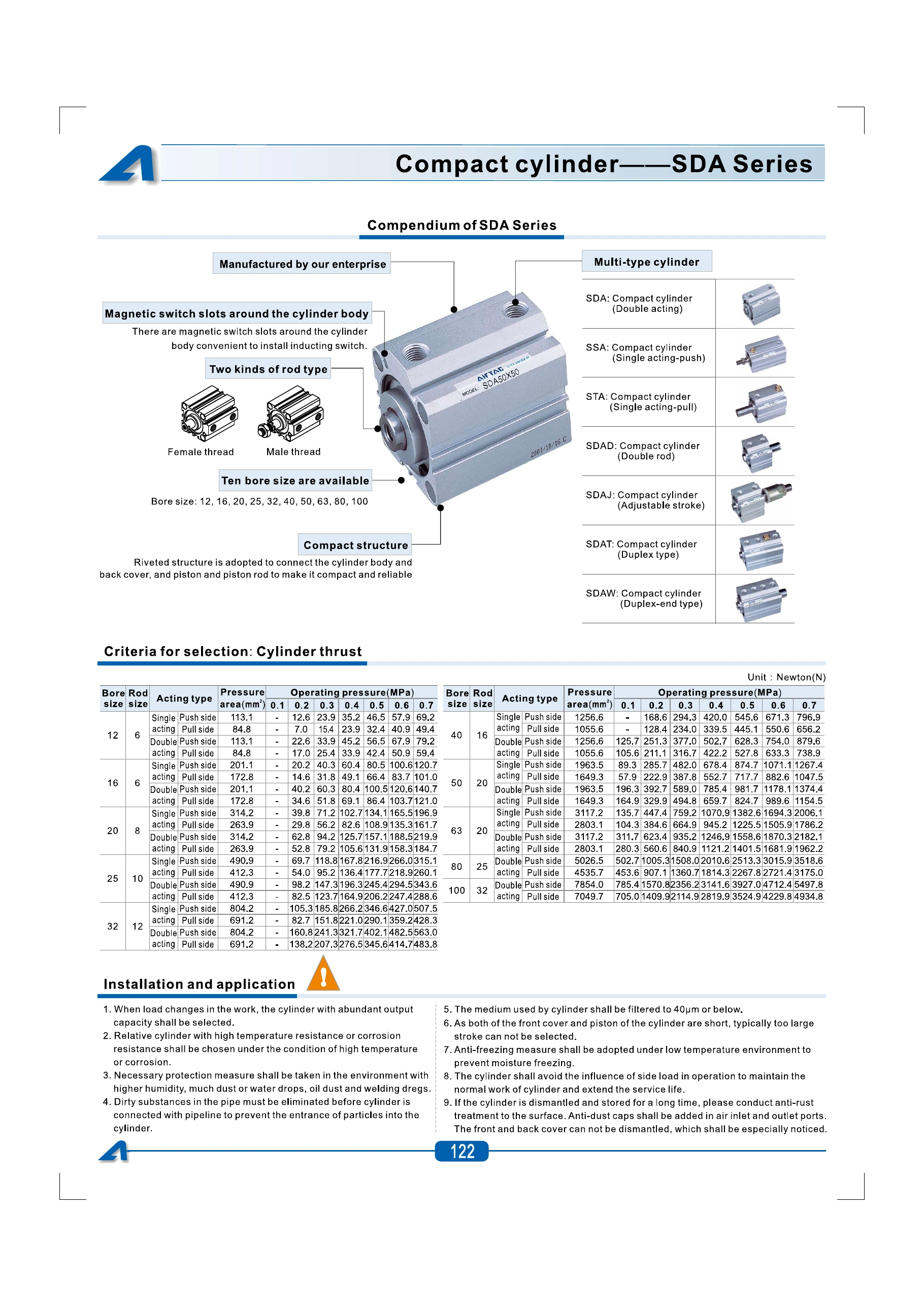
Technical reference: AirTAC official 2024 file, printed pp.122–127. Confirm the offered complete model and current drawing before ordering, including the printed SDAT 16 mm bore PA value at 5 mm stroke. Catalog data and the series photograph do not establish JEMWON manufacture, independent certification or cross-brand fit.
Check working force and the full travel envelope.
Available pressure, load direction and required motion determine the selection. Compact body length alone does not establish mounting fit or the installed space needed by a double rod, adjustment mechanism or two-stroke arrangement.
- Load and direction
- Provide load, orientation, pressure at the cylinder, stroke and travel time. Check the relevant push or pull force and leave capacity for losses and changing load.
- Acting and return
- Specify double acting, SSA air-driven push or STA air-driven pull. Single-acting ranges and forces do not extend to 80/100 mm; confirm the required return behavior for the offered model.
- Mounting and side load
- Compare hole pattern, rod thread, air connection and the full moving envelope. Keep side load off the piston rod and provide external guidance where needed.
- Magnet and duplex travel
- Specify magnet and sensor requirements. For SDAT/SDAW provide both strokes and verify their sum against the standard-stroke table and their separate length formula.
- Air and installation
- Use filtered air and clear the pipework before connection. Check moisture, temperature, protection from contamination and maintenance requirements for the actual installation.
| Bore (mm) | Rod Ø (mm) | Double-acting push (N) | Double-acting pull (N) | SSA push-direction reference (N) | STA pull-direction reference (N) |
|---|---|---|---|---|---|
| 12 | 6 | 56.5 | 42.4 | 46.5 | 32.4 |
| 16 | 6 | 100.5 | 86.4 | 80.5 | 66.4 |
| 20 | 8 | 157.1 | 131.9 | 134.1 | 108.9 |
| 25 | 10 | 245.4 | 206.2 | 216.9 | 177.7 |
| 32 | 12 | 402.1 | 345.6 | 346.6 | 290.1 |
| 40 | 16 | 628.3 | 527.8 | 545.6 | 445.1 |
| 50 | 20 | 981.7 | 824.7 | 874.7 | 717.7 |
| 63 | 20 | 1558.6 | 1401.5 | 1382.6 | 1225.5 |
| 80 | 25 | 2513.3 | 2267.8 | — | — |
| 100 | 32 | 3927.0 | 3524.9 | — | — |
Values are transcribed from the 0.5 MPa catalog column, without recalculation. SSA push and STA pull refer to different single-acting arrangements and their air-driven working direction; they are not the pneumatic out/back forces of one single-acting cylinder or a spring-return force rating. Allow for friction, load variation and pressure loss; duplex output is not inferred from this table.
Scroll the table horizontally to compare all columns.
Specify the complete compact-cylinder configuration.
Include model, bore, acting type, stroke, magnet, female or male rod, thread, pressure, load, mounting, sensor and quantity. Add adjustable travel for SDAJ or both strokes for SDAT/SDAW. For a replacement, include the full old code, current drawing and measured installation dimensions.
The brief tool creates text on your device to copy or download. It does not send an online enquiry.
Does a magnet change only the sensor option?
No. The reference lists different standard-stroke limits and A/AC body dimensions with and without a magnet. Select the correct columns and confirm the sensor separately.
Can SSA or STA be selected at 80 or 100 mm bore?
The documented SSA push and STA pull range is 12–63 mm. The 80/100 mm rows list double acting only; confirm an alternative configuration for a larger single-acting requirement.
How should I specify an SDAT or SDAW cylinder?
Provide stroke 1 and stroke 2 separately. Their sum must not exceed the value in the reference standard-stroke table. Use the selected duplex drawing because SDAT and SDAW have different overall-length formulas and air-port layouts.
What should I check for a replacement cylinder?
Confirm the complete code, acting type, bore, stroke, magnet, rod thread, mounting holes, port thread and travel envelope against the current supplier drawing. A series name or matching bore alone does not establish replacement fit.