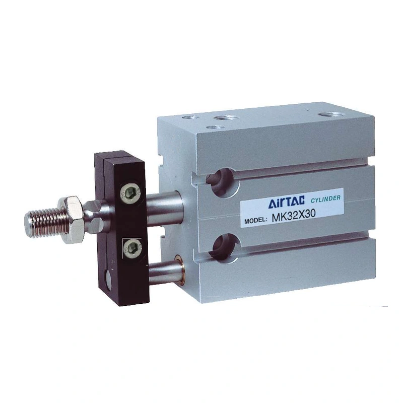
MK Series Non-Rotating Multi-Mount Cylinders
A multi-mount cylinder family with a front non-rotating plate and fixed rods around a round piston rod. Select single-rod, single-acting, double-rod or adjustable-stroke configurations, then check pressure, mounting and the full moving envelope.
- Documented bores
- 6–32 mm
- Configurations
- MK / MSK / MTK / MKD / MKJ
- Non-rotating arrangement
- Front plate and fixed rods
Check the bore-specific pressure and acting direction.
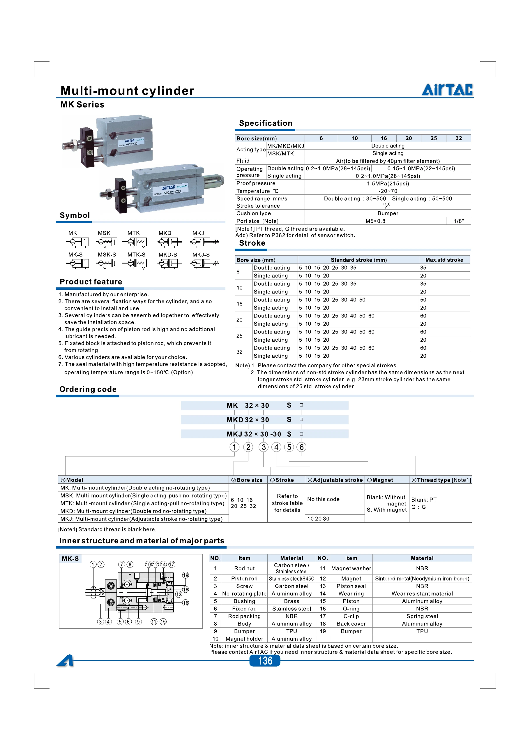
The AirTAC reference separates the smaller double-acting pressure range from 16–32 mm bores. MSK/MTK have their own single-acting conditions and standard strokes. Confirm the complete offered model before applying a row.
| Parameter | Catalog reference |
|---|---|
| Working medium | Air filtered through a 40 μm element |
| MK / MKD / MKJ pressure, 6 / 10 mm bore | 0.2–1.0 MPa |
| MK / MKD / MKJ pressure, 16–32 mm bore | 0.15–1.0 MPa |
| MSK / MTK operating pressure | 0.2–1.0 MPa |
| Proof pressure | 1.5 MPa |
| Standard temperature | −20 to +70 °C |
| Double-acting speed | 30–500 mm/s |
| Single-acting speed | 50–500 mm/s |
| Stroke tolerance | +1.0 / 0 mm |
| Cushioning | Bumper |
Select the double-acting pressure row by bore. Proof pressure is a test value; confirm the complete offered configuration and operating conditions. The standard temperature range does not rate an optional high-temperature configuration.
| Bore (mm) | Nominal air connection |
|---|---|
| 6 | M5 × 0.8 |
| 10 | M5 × 0.8 |
| 16 | M5 × 0.8 |
| 20 | M5 × 0.8 |
| 25 | M5 × 0.8 |
| 32 | 1/8″ |
M5 connections are metric. This reference lists blank PT or G for pipe connections; confirm the actual supplied thread and complete code before ordering. Rc and NPT are not established by this reference.
Scroll the table horizontally to compare all columns.
| Bore (mm) | Arrangement | Listed standard strokes (mm) | Max. standard stroke (mm) |
|---|---|---|---|
| 6 | MK / MKD / MKJ double acting | 5 10 15 20 25 30 35 | 35 |
| 6 | MSK / MTK single acting | 5 10 15 20 | 20 |
| 10 | MK / MKD / MKJ double acting | 5 10 15 20 25 30 35 | 35 |
| 10 | MSK / MTK single acting | 5 10 15 20 | 20 |
| 16 | MK / MKD / MKJ double acting | 5 10 15 20 25 30 40 50 | 50 |
| 16 | MSK / MTK single acting | 5 10 15 20 | 20 |
| 20 | MK / MKD / MKJ double acting | 5 10 15 20 25 30 40 50 60 | 60 |
| 20 | MSK / MTK single acting | 5 10 15 20 | 20 |
| 25 | MK / MKD / MKJ double acting | 5 10 15 20 25 30 40 50 60 | 60 |
| 25 | MSK / MTK single acting | 5 10 15 20 | 20 |
| 32 | MK / MKD / MKJ double acting | 5 10 15 20 25 30 40 50 60 | 60 |
| 32 | MSK / MTK single acting | 5 10 15 20 | 20 |
Other special strokes require confirmation. The reference uses the next longer standard-stroke envelope for a non-standard stroke; its example is 23 mm using the 25 mm standard envelope. Do not treat the maximum standard stroke as a confirmed limit for every special configuration.
Scroll the table horizontally to compare all columns.
Select the acting, magnet and adjustment fields.
MSK uses air-driven push and MTK uses air-driven pull. MKD adds a rear rod; MKJ adds stroke adjustment. Confirm the complete non-rotating assembly, its sensor and actual connection thread.
Non-rotating model arrangements
| Code | Catalog arrangement | Documented bores (mm) |
|---|---|---|
| MK | Double acting, non-rotating | 6 10 16 20 25 32 |
| MSK | Single acting, air-driven push, non-rotating | 6 10 16 20 25 32 |
| MTK | Single acting, air-driven pull, non-rotating | 6 10 16 20 25 32 |
| MKD | Double rod, non-rotating | 6 10 16 20 25 32 |
| MKJ | Adjustable stroke, non-rotating | 6 10 16 20 25 32 |
The illustrated non-rotating arrangement uses a front plate and fixed rods around a round piston rod. The reference does not provide angular-accuracy or allowable-torque ratings; confirm those requirements for the offered assembly.
Scroll the table horizontally to compare all columns.
Ordering fields
| Field | Catalog choices |
|---|---|
| Bore | 6 10 16 20 25 32 |
| Stroke | Use the selected bore and acting-type stroke row |
| Adjustable stroke | MKJ only: 10 20 30 mm; no adjustment field for MK / MSK / MTK / MKD |
| Magnet | Blank: without magnet; S: with magnet |
| Pipe thread | Blank: PT; G: G thread |
M5 air connections are metric. Confirm the complete supplied model, thread, magnet, sensor and current drawing. The illustrated male rod end does not establish an additional rod-end ordering option.
Scroll the table horizontally to compare all columns.
MK-S internal material reference
| No. / part | Catalog material |
|---|---|
| 1 Rod nut | Carbon steel / stainless steel |
| 2 Piston rod | Stainless steel / S45C |
| 3 Screw | Carbon steel |
| 4 Non-rotating plate | Aluminum alloy |
| 5 Bushing | Brass |
| 6 Fixed rod | Stainless steel |
| 7 Rod packing | NBR |
| 8 Body | Aluminum alloy |
| 9 Bumper | TPU |
| 10 Magnet holder | Aluminum alloy |
| 11 Magnet washer | NBR |
| 12 Magnet | Sintered metal (neodymium-iron-boron) |
| 13 Piston seal | NBR |
| 14 Wear ring | Wear-resistant material |
| 15 Piston | Aluminum alloy |
| 16 O-ring | NBR |
| 17 C-clip | Spring steel |
| 18 Back cover | Aluminum alloy |
| 19 Bumper | TPU |
The source states that this illustrated structure and material sheet is based on a particular bore. Confirm the required bore and offered configuration; slash-separated rod/nut alternatives are not assigned to individual bores here. This reference is not a material certificate.
Scroll the table horizontally to compare all columns.
MK specification, ordering and structure reference
Match the plate, guides and complete cylinder envelope.
Dimensions are in millimetres except identified threads. Open the matching model group and select magnet-specific lengths. MSK/MTK use stroke-specific A/AC values; MKD/MKJ use separate A and DB columns and rear-clearance formulas. Confirm unlisted variant interfaces on the current mounting drawing.
MK body, front plate and mounting dimensions
| Bore (mm) | A no magnet | AC no magnet | A with magnet | AC with magnet | B | C | D | DA | E |
|---|---|---|---|---|---|---|---|---|---|
| 6 | 51 | 33 | 51 | 33 | 16.5 | 22 | 3 | 18 | M3 × 0.5 |
| 10 | 57 | 36 | 57 | 36 | 16.5 | 24 | 4 | 21 | M4 × 0.7 |
| 16 | 56 | 30 | 66 | 40 | 20 | 32 | 6 | 26 | M5 × 0.8 |
| 20 | 65 | 36 | 75 | 46 | 26 | 40 | 8 | 29 | M6 × 1.0 |
| 25 | 73 | 40 | 83 | 50 | 32 | 50 | 10 | 33 | M8 × 1.25 |
| 32 | 84 | 42 | 94 | 52 | 40 | 62 | 12 | 42 | M10 × 1.25 |
Dimensions in mm except identified threads. Select the magnet-specific A/AC columns. The drawing labels overall length A + stroke and body length AC + stroke. D identifies the round piston rod; the front plate and fixed rods provide the non-rotating arrangement.
Scroll the table horizontally to compare all columns.
| Bore (mm) | EA | EB | F | FA | G | GA | GB | GC | GD | H | J | JA |
|---|---|---|---|---|---|---|---|---|---|---|---|---|
| 6 | 7 | 8 | 5.5 | 2.5 | 8 | 9 | 11 | 19 | 10.7 | — | 6 | 5 |
| 10 | 10 | 11 | 7 | 2 | 8 | 12 | 13 | 20.5 | 11.6 | — | 6 | 5.5 |
| 16 | 11 | 12.5 | 8 | 4 | 8 | 17 | 13 | 26.5 | 15.6 | 5 | 7.5 | 6.5 |
| 20 | 12 | 14 | 10 | 5 | 8 | 20 | 16 | 32 | 19.5 | 6 | 9.5 | 8 |
| 25 | 15.5 | 18 | 12 | 6 | 10 | 22 | 19 | 40 | 24.5 | 8 | 9.5 | 9 |
| 32 | 19.5 | 22 | 17 | 6 | 12 | 29 | 24 | 49 | 30.5 | 10 | 11 | 11.5 |
Check the plate width, guide spacing and front fixing clearance against the labelled drawing. A dash means the reference does not list that dimension; it is not zero.
Scroll the table horizontally to compare all columns.
| Bore (mm) | JB | JC | K | KB | L | LA | LB | P | PA | PB | PC |
|---|---|---|---|---|---|---|---|---|---|---|---|
| 6 | 10 | 7 | 3.3 | 7 | M3 × 0.5 | 5 | 17 | M5 × 0.8 | 14 | 10 | — |
| 10 | 11 | 7 | 3.3 | 9 | M3 × 0.5 | 5 | 18 | M5 × 0.8 | 15.5 | 10 | — |
| 16 | 14 | 7 | 4.5 | 12 | M4 × 0.7 | 5 | 25 | M5 × 0.8 | 14.5 | 10 | 3 |
| 20 | 16 | 9 | 5.5 | 16 | M5 × 0.8 | 7.5 | 30 | M5 × 0.8 | 19.3 | 9.5 | 9 |
| 25 | 20 | 10 | 5.5 | 20 | M5 × 0.8 | 8 | 38 | M5 × 0.8 | 20.5 | 8.5 | 12 |
| 32 | 24 | 11 | 6.5 | 24 | M6 × 1.0 | 9 | 48 | 1/8″ | 22 | 12.5 | 13 |
Dimensions in mm except identified threads. Confirm hole type, thread depth and port orientation from the selected current drawing; pipe-thread type must be specified with the complete model.
Scroll the table horizontally to compare all columns.
MSK / MTK single-acting dimensions
| Bore (mm) | A no magnet, 5 mm stroke | A no magnet, 10 mm stroke | A no magnet, 15 mm stroke | A no magnet, 20 mm stroke | A with magnet, 5 mm stroke | A with magnet, 10 mm stroke | A with magnet, 15 mm stroke | A with magnet, 20 mm stroke |
|---|---|---|---|---|---|---|---|---|
| 6 | 61 | 66 | 76 | 81 | 61 | 66 | 76 | 81 |
| 10 | 67 | 72 | 82 | 87 | 67 | 72 | 82 | 87 |
| 16 | 71 | 76 | 91 | 96 | 81 | 86 | 101 | 106 |
| 20 | 80 | 85 | 100 | 105 | 90 | 95 | 110 | 115 |
| 25 | 88 | 93 | 108 | 113 | 98 | 103 | 118 | 123 |
| 32 | 99 | 104 | 119 | 124 | 109 | 114 | 129 | 134 |
Select the listed stroke-specific A/AC values. The MSK drawing labels overall length A; the MTK drawing labels A + stroke. Other unmarked dimensions follow the MK standard-type drawing as stated in the source. Confirm the complete envelope for the selected acting direction.
Scroll the table horizontally to compare all columns.
| Bore (mm) | AC no magnet, 5 mm stroke | AC no magnet, 10 mm stroke | AC no magnet, 15 mm stroke | AC no magnet, 20 mm stroke | AC with magnet, 5 mm stroke | AC with magnet, 10 mm stroke | AC with magnet, 15 mm stroke | AC with magnet, 20 mm stroke |
|---|---|---|---|---|---|---|---|---|
| 6 | 43 | 48 | 58 | 63 | 43 | 48 | 58 | 63 |
| 10 | 46 | 51 | 61 | 66 | 46 | 51 | 61 | 66 |
| 16 | 45 | 50 | 65 | 70 | 55 | 60 | 75 | 80 |
| 20 | 51 | 56 | 71 | 76 | 61 | 66 | 81 | 86 |
| 25 | 55 | 60 | 75 | 80 | 65 | 70 | 85 | 90 |
| 32 | 57 | 62 | 77 | 82 | 67 | 72 | 87 | 92 |
Select the listed stroke-specific A/AC values. The MSK drawing labels overall length A; the MTK drawing labels A + stroke. Other unmarked dimensions follow the MK standard-type drawing as stated in the source. Confirm the complete envelope for the selected acting direction.
Scroll the table horizontally to compare all columns.
MKD / MKJ double-rod and adjustable dimensions
| Bore (mm) | MKD A no magnet | MKJ A no magnet | MKD A with magnet | MKJ A with magnet | AC no magnet | AC with magnet | AE | B | C | D | DA | MKD DB | MKJ DB | E |
|---|---|---|---|---|---|---|---|---|---|---|---|---|---|---|
| 6 | 75 | 75 | 75 | 75 | 38 | 38 | 6 | 16.5 | 22 | 3 | 18 | 13 | 13 | M3 × 0.5 |
| 10 | 79 | 78 | 79 | 78 | 36 | 36 | 6 | 16.5 | 24 | 4 | 21 | 16 | 14.7 | M4 × 0.7 |
| 16 | 79.5 | 80.5 | 89.5 | 90.5 | 30 | 40 | 7.5 | 20 | 32 | 6 | 26 | 16 | 17 | M5 × 0.8 |
| 20 | 93 | 95 | 103 | 105 | 36 | 46 | 9 | 26 | 40 | 8 | 29 | 19 | 21 | M6 × 1.0 |
| 25 | 105 | 107 | 115 | 117 | 40 | 50 | 9 | 32 | 50 | 10 | 33 | 23 | 25 | M8 × 1.25 |
| 32 | 121 | 121 | 131 | 131 | 42 | 52 | 10 | 40 | 62 | 12 | 42 | 27 | 27 | M10 × 1.25 |
Use the separate MKD/MKJ A and DB columns. MKD overall length is A + 2 × stroke; its rear projection is DB + stroke. MKJ overall length is A + 2 × stroke + adjustable stroke; rear labels are DB + adjustable stroke and DB + stroke + adjustable stroke. Both body drawings use AC + stroke.
Scroll the table horizontally to compare all columns.
| Bore (mm) | EA | EB | F | FA | G | GA | GB | GC | GD | H | J | JA | JB | JC | K | KB | P | PA | PB | PC |
|---|---|---|---|---|---|---|---|---|---|---|---|---|---|---|---|---|---|---|---|---|
| 6 | 7 | 8 | 5.5 | 2.5 | 8 | 9 | 11 | 19 | 10.7 | — | 6 | 5 | 10 | 7 | 3.3 | 7 | M5 × 0.8 | 14 | 16 | — |
| 10 | 10 | 11 | 7 | 2 | 8 | 12 | 13 | 20.5 | 11.6 | — | 6 | 5.5 | 11 | 7 | 3.3 | 9 | M5 × 0.8 | 15.5 | 16 | — |
| 16 | 11 | 12.5 | 8 | 4 | 8 | 17 | 13 | 26.5 | 15.6 | 5 | 7.5 | 6.5 | 14 | 7 | 4.5 | 12 | M5 × 0.8 | 14.5 | 17.5 | 3 |
| 20 | 12 | 14 | 10 | 5 | 8 | 20 | 16 | 32 | 19.5 | 6 | 9.5 | 8 | 16 | 9 | 5.5 | 16 | M5 × 0.8 | 19.3 | 18.5 | 9 |
| 25 | 15.5 | 18 | 12 | 6 | 10 | 22 | 19 | 40 | 24.5 | 8 | 9.5 | 9 | 20 | 10 | 5.5 | 20 | M5 × 0.8 | 20.5 | 17.5 | 12 |
| 32 | 19.5 | 22 | 17 | 6 | 12 | 29 | 24 | 49 | 30.5 | 10 | 11 | 11.5 | 24 | 11 | 6.5 | 24 | 1/8″ | 22 | 22.5 | 13 |
Dimensions in mm except identified threads. This variant reference does not list L/LA/LB mounting-thread dimensions; obtain the current variant mounting drawing before fixing those interfaces. Do not substitute MD or base-MK values for an unlisted variant dimension.
Scroll the table horizontally to compare all columns.
MK, MSK, MTK, MKD and MKJ drawings and dimensions
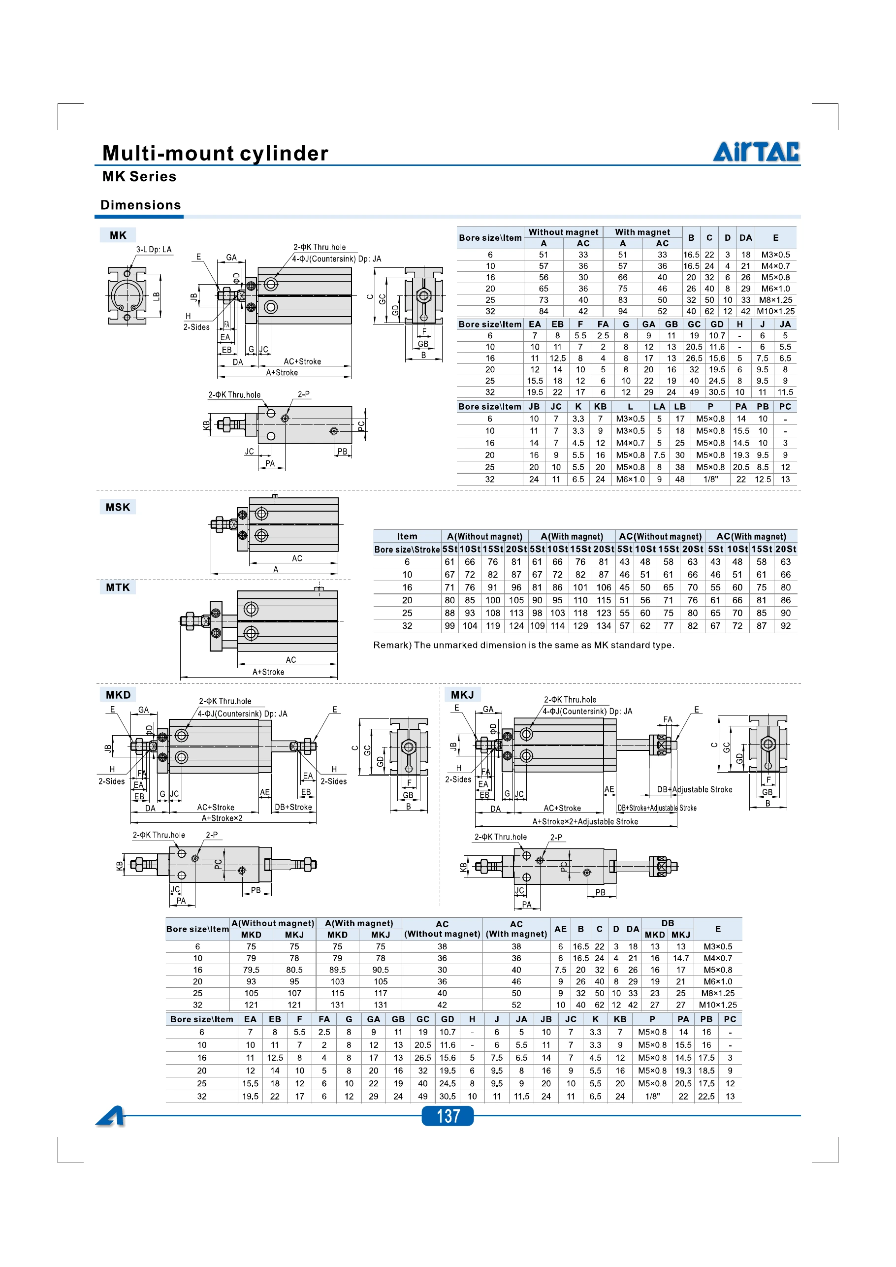
Technical reference: AirTAC catalog, printed pp.136–137. This identifies a reference publication, not a confirmed current revision of the offered cylinder. Confirm the complete model, thread, magnet, load/moment ratings and current installation drawing before ordering. Catalog data and photographs do not establish JEMWON manufacture, independent certification or cross-brand replacement fit.
Confirm the applied moment and moving clearances.
A non-rotating arrangement does not by itself establish a permitted torque, angular accuracy or side-load rating. Provide the force, load arm and alignment requirement alongside pressure, stroke and mounting conditions.
- Moment and angular requirement
- Provide applied torque or moment, lateral load, load arm, mounting orientation and permissible rotation. Request the ratings and current drawing for the offered assembly; the reference publishes no numerical angular accuracy or allowable torque.
- Acting and return direction
- Specify double acting, MSK air-driven push or MTK air-driven pull. Include load, working pressure at the cylinder, travel time and required return behavior.
- Plate and mounting interface
- Compare front plate geometry, fixing holes, guide clearances and air-port positions to the machine. Obtain missing MKD/MKJ mounting-thread details rather than assuming the base-MK or MD interface.
- Magnet and sensor
- Specify whether the magnet is required and choose the corresponding A/AC dimensions. Confirm the sensor model, location and electrical arrangement separately.
- Rear rod and adjustment
- For MKD include rear rod travel. For MKJ specify both main and adjustable stroke and allow for the complete adjustment assembly throughout travel.
- Air and environment
- Confirm filtration, temperature, moisture and contamination protection for the actual service. A high-temperature seal option requires separate selection and does not change the standard rating automatically.
Define one complete non-rotating cylinder requirement.
Include model, bore, acting direction, main and adjustable stroke, magnet, actual thread, mounting, pressure, load, moment/load arm, permissible rotation, sensor and quantity. For replacement include the full old code, current drawing and measured plate, fixing and clearance dimensions.
The brief tool creates text on your device to copy or download. It does not send an online enquiry.
What provides the non-rotating arrangement?
The illustrated MK construction uses a front plate and fixed rods around a round piston rod. Confirm the complete assembly, permitted torque and angular accuracy against the current model documentation.
Can MKD and MKJ use the base-MK installation length?
Use the separate variant table and its MKD/MKJ A and DB columns. MKD includes rear rod travel; MKJ also includes adjustable-stroke clearance. Unlisted variant mounting-thread details require a current drawing.
Does a magnet change the envelope?
The listed magnetic and non-magnetic A/AC values match at 6/10 mm and differ at 16–32 mm. Single-acting lengths also depend on the selected standard stroke. Confirm the actual sensor separately.
Which pressure and pipe-thread row applies?
For MK/MKD/MKJ, the reference lists 0.2–1.0 MPa at 6/10 mm and 0.15–1.0 MPa at 16–32 mm. MSK/MTK use 0.2–1.0 MPa. M5 connections are metric; the 32 mm nominal pipe connection is 1/8 inch with blank PT/G choices in this reference. Confirm the actual supplied code and thread.